Harjoitus: Älykkäitä vaatteita

Johdanto

Erilaisissa älyvaatteissa (wearables) tavallisten aktiivisuusrannekkeiden ja älykellojen toimintoja siirretään suoraan vaatteisiin. Vaatteisiin ja vaikkapa kenkiin kiinnitetyt sensorit voivat pitää kirjaa askeleista, lämpötilasta, asennoista tai sijainnista ja vaikkapa ohjata vaatteisiin kiinnitettyjä ledejä vaihtamaan väriään tämän pohjalta.

Tässä harjoituksessa pääset kokeilemaan yksinkertaista wearables-projektia. Tarvitset sähköä johtavaa lankaa, ledejä ja boardin, jonka pinneihin voi kiinnittää sähköä johtavaa lankaa esimerkiksi solmimalla.

Harjoituksessa opastetaan etenkin Lilypad LilyMini (ProtoSnap) käyttöön, mutta pärjäät hyvin millä tahansa LilyPadilla tai tarvittaessa muullakin kevyehköllä boardilla. Yleensä wearables-projekteissa käytettävät boardit ovat suhteellisen pieniä ja huomaamattomia, koska niiden on tarkoitus kulkea vaatteiden mukana turhaa huomiota herättämättä.

Alla olevalla videolla on LilyPadilla tehty wearables-projekti inspiraatioksi.

Taylor Sparks: Arduino Lilypad Death Star Christmas Sweater

Tekstitykset

okay this is the beginning the beginning of an epic project Atticus gonna count we already started making it Evie's gonna help me too we drew up art designs we ordered the parts got a bunch of lily patty textiles time to get started okay step one to make sewing easier you get a little frame for like cross stitching so we installed our battery make sure that we have power look at this sure enough just to test that we've got power running to be able to light up our LED so we got power that's first step now let's test to see if we can make it do a basic program okay we already hooked up power we figured out how to get the battery working we tried making the internal LED flash now we've done some basic stitching here we took our bank of LEDs and we stitched all the positives together we ran all the negatives to the ground and we've got a basic program running with all these from each port in the sweater that we make we're gonna have about five LEDs they're all going to be the same type so they'll have the same current drop across them these have slightly different voltages so they're drawing slightly different voltages or currents but it clearly is enough to show that this is going to work fine I was afraid it would be bright enough with the 40 milliamps that each port can put out but seems to not be a problem right now okay I've got the got the accelerometer stitched in now that's connected to the ground of the LED bank they've got power from the Tamiya battery and now we've got a simple program written where it's gonna monitor the Y component of the accelerometer in real time and as we lift it if we lift it above a certain threshold angle that we've programmed in it's gonna start to flash all right so I've got a tilt it up and that's the trigger for it to flash when I lower it down again it's off and it's running in real time all powered by the lithium battery right now okay check it out in the background we have pulsating we'll have a bunch of these all over the front of the sweater this will be like the stars of the galaxy all pulsing I'll have only white ones though and then when the arm gets raised up over a certain degree down the sleeve you'll have a bunch of things blasting they won't all be together they'll go in a row like doo-doo-doo but for now I've got them just wired together so we have a proof of concept it worked on this t-shirt with some crappy sewing so now we need a sweatshirt and we need to do some legit selling and it's gonna be sweet okay step 1 now that we got the co-working and we did a prototype we got a nice new sweater we're gonna have the Deathstar right here so we got some nice fabric for the Deathstar got a whole bunch of grays to look at we're kind of leaning towards this one because it's got this cool grid pattern by time you make a skull out of that put some black thread on it it's gonna look like a sweet death star [Music] okay we've got the sweater we've got a potential death star lay down there what we're gonna do is we're gonna take this off for right now we're just gonna make this thing sew it on we're gonna do all the contacts or make all these connections all right make all these connections first and then when all that's done there's gonna have a ton of wires coming off it we'll cover that up with this thing and we're just going to fuse that on okay so to these sleeves since we're gonna do a kind of complex pattern they're gonna be easier to so if we just unstitch it so use your handy dandy on stitcher tool they seem a ripper me rip those teams okay what we've decided to do first is we're gonna holster the battery down here so this we're gonna stitch a little pocket for it this thing that's it right like there which will allow us to wire into the positive and negative lines I've gone through and stitched in or I've drawn in red and black lines to represent where the positive and negative leads are going to go to power the accelerometer on either sleeve as well as the lines for the LEDs drew some patterns down and got an idea of where we want the thread to go we're putting down the negative lines first and the conductive thread is in the bobbin so it's showing up on the inside of the shirt and on the outside we've got a nice barek thread that you can't even see it's basically invisible up here so you can't just even see where you put it down now as you're sewing you're going to need to make sure that your positives and your negatives aren't getting crossed or you're going to short-circuit your thing so for example here we wanted this line to go through but I had to jump over another one so we put down some hot glue and some felt when I touch it over here I have contact right but that's not shorting over here it's still over one so I've got contact where I need it to be and I've got it short and I've got no contact right down here to me you need to test to make sure that these lines aren't shorting on one another in this case this line here was shorting with this line at this point so I made a cut here and I'm going to bypass it and come over and I'm going to reconnect it there to fix the short now that we have the wines running on the inside I decided would be easier if I went ahead and I hot-glued these into place with a hot glue gun so these are now in place I've got them on both sides running up and all the way down I need to do the same on that arm over here okay now that we've we want to do you want to test to see if it has connectivity I'm going to take this I'm going to hold it in the pin number one right there I'm gonna test it against I'm gonna test to see if it's connecting so right here it should be not connecting and sure enough the dial is still at overload same over here say however on this one where it should be connecting it's reading a value over here it's not nothing nothing nothing nothing you okay the copper wire is not the worst thing ever it works you can send it down there and sort of bundle as you go it's not ideal but it'll work okay it's actually kind of nice to solder onto things that holds pretty well I made one big common wire here so that I can put all my grounded wires to you okay with the arms done all right these need to be sewed in still but the arms are both done now we can turn our attention to the middle right so I hot-glued a bunch of these things down and I've got them twinkling in and out of phase with one another so the Sun go down mothers go bright I need to finish these ones right I'm using the pwm pins over here so this is pin number 10 nine six and five those are the four PW pins that I'm using for this and by tomorrow night this thing should be done okay so in its current form it's working we've got four different sets of lights on the front which like the stars twinkling I still need to put the Death Star on here and if I raise my arm I get these things to pulse two of the bed bands of LED still neither so dog you know we're here for the same thing also go to need to be connected still these ones need to be connected to the ports you can't do that while you're loading the program onto it yep both up they both go one after another they both down and normal neither one goes and these things go back to complain the final touches on the sweater was to add the Deathstar which I drew on this fabric that sort of had a grid-like pattern to it I made sure to leave the opening for the blaster to be where there are three no sets and now it looked kind of like it's blasting lasers when you lift this arm up which is pretty darn sweet you okay after making all the correction final product the middle has twinkles you've got the death star with a lily pad in the middle I fixed everything it's a bit wrinkled up because the tape inside and when you grab these not even enough lift those up synchronised they both now light up in a synchronized manner until you let them down okay about that they caught us and you let them down they stop thanks Bob
Tarvikkeet

Voit tehdä tämän harjoituksen periaatteessa millä tahansa boardilla, jonka digitaalisen pinnit ovat reikiä. Reiät ovat tarpeen, koska tulet solmimaan niihin sähköä johtavaa lankaa ja kiinnittämään ledit toisiin päihin. Lilypad-sarjan boardit on erityisesti suunniteltut tätä tarkoitusta ja ommeltavaa elektroniikkaa varten.

OsaKuvaKuvaus
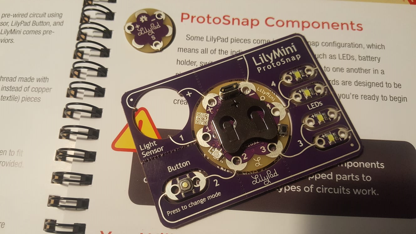
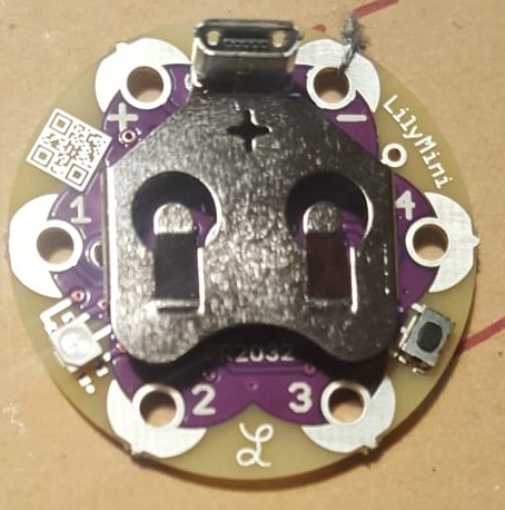
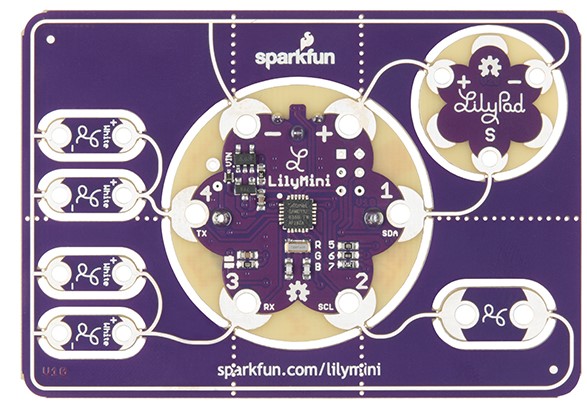
Lilypad LilyMini (ProtoSnap)LilyMini Protosnap on oikeastaan valmis virtapiiri, jossa varsinaiseen pieneen pyöreään boardiin (kuvassa keskellä) on kiinnitetty muutamia ledejä, nappi ja valovastus jo valmiiksi. Boardin ja komponentit saa kuitenkin taitettua irti virtapiiristä, jotta niitä voi käyttää jatkossa oman mielensä mukaan!
USB-Micro USB -johtoTietokoneella kirjoitettu ohjelma lähetetään LilyMinille USB-johdolla, jonka toisessa päässä on MIcro USB -liitin
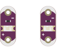
Ledejä ja vastuksiaLilypad-kitissä on mukana jo valmiiksi vastuksen sisältäviä ledejä, joihin saa kätevästi kiinni sähköä johtavan langan solmimalla. ProtoSnapissa on muutamia ledejä myös valmiiina (4 kpl ProtoSnapin vasemmassa reunassa.
Sähköä johtavaa lankaa (conductive thread)Koponenttien liittämiseen ja solmimiseen.
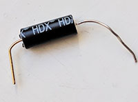
Tilt-kytkinKallistukseen reagoiva kytkin. Voit käyttää myös jotain muuta kytkintä tai anturia harjoituksessa.

Ohjelmointi 1/2: LilyMinin testaus

Aluksi muodostetaan yhteys Arduino IDEn ja ohjelmoitavan boardin välille.

Jos käytössäsi on LilyMini (tai LilyMini Protosnap), seuraa alla linkatun tutoriaalin ohjeita otsikkoon Recovery Mode saakka. Ohjeessa kerrotaan, miten saat Arduino IDEn tunnistamaan LilyMinin sen ohjelmointia varten.

HUOM!

Yllä linkatussa tutoriaalissa asennetaan Tools > Board > Boards Manager kautta kaksi eri board-pakettia. Asenna ensin Arduino SAMD Boards -paketti versiona 1.6.14 ja vasta tämän jälkeen SparkFun SAMD Boards -paketti versiona 1.4.0.

Jos asennat paketit eri järjestyksessä tai asennat niistä eri versiot, Lilypad Minin ohjelmointi ei luultavasti onnistu. Poista tällöin pakettien asennukset klikkaamalla pakettia Boards Manager -valikosa ja painamalla Remove. Voit valita paketin version asennuksen yhteydessä klikkaamalla pakettia ja painamalla Select Version > Oikea versio > Install.

Avaa kirjastojen asentamisen jälkeen Arduino IDE:stä

File > Examples > LilyMini_Guide > LilyMini_1_Blink

Yhdistä LilyPad tietokoneeseesi Micro USB-piuhalla ja syötä sille koodi. Esimerkin pitäisi vilkuttaa LilyMinin lediä. Tutustu esimerkin koodiin.

Käy tämän jälkeen läpi myös muut esimerkit LilyMini_Guide -valikosta (Button, NightLight ja LightSensor). Button-esimerkissä otetaan käyttöön LilyMinin nappi, ja Nightlight ja Light Sensor opastavat käyttämään LilyMiniin kiinnitettyä valosensoria. Tutustu näiden esimerkkien koodiin.

Sähköä johtava lanka

Olet aiemmin luultavasti käyttänyt virtapiirien tekemiseen muovilla päällystettyjä sähköjohtimia, joita olet yhdistellyt koekytkentälevyn kautta. Sähköjohtimia on kuitenkin hyvin monenlaisia, ja joihinkin käyttötarkoituksiin tavalliset sähköjohtimet ovat hieman kömpelöitä.

Sähköä johtava lanka voi olla valmistettu esimerkiksi hopeasta, teräksestä tai muusta sähköä johtavasta materiaalista. Lanka toimii kuin sähköjohto, mutta etuna on, että voit solmia sen kiinni komponentteihin ja myös ommella komponentit näin kiinni kankaisiin. Lanka on huomaamattomampi ja kevyempi ratkaisu kuin sähköjohtimet. Lisätietoa langasta löydät esimerkiksi Sparkfunin sivuilta täältä.

Tässä harjoituksessa pääset kokeilemaan komponenttien solmimista langan avulla. Komponenttien ompelua kankaisiin voit halutessasi kokeilla tämän kurssin projektissasi.

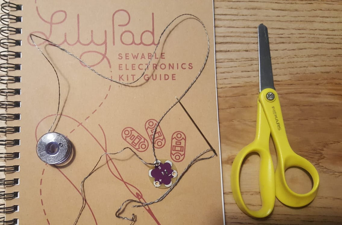
Jos sinulla on jokin Lilypad-kitti, löydät sieltä luultavasti ohjeita hyvien ompeleiden ja solmujen tekemiseen. Pääasia kuitenkin on, että sinulta löytyy kuvassa näkyvän kaltainen rulla sähköä johtavaa lankaa. Langan katkaisu käy kätevimmin saksilla, ja neula voi auttaa myös solmimisessa.

LilyMini ProtoSnapin purkaminen

Kun olet kokeillut LilyMinin tai Lilypadin ohjelmointia onnistuneesti, on aika kehitellä jokin hauska toiminto, joka sytyttää esimerkiksi vaatteisiisi kiinnitettyjä ledejä.

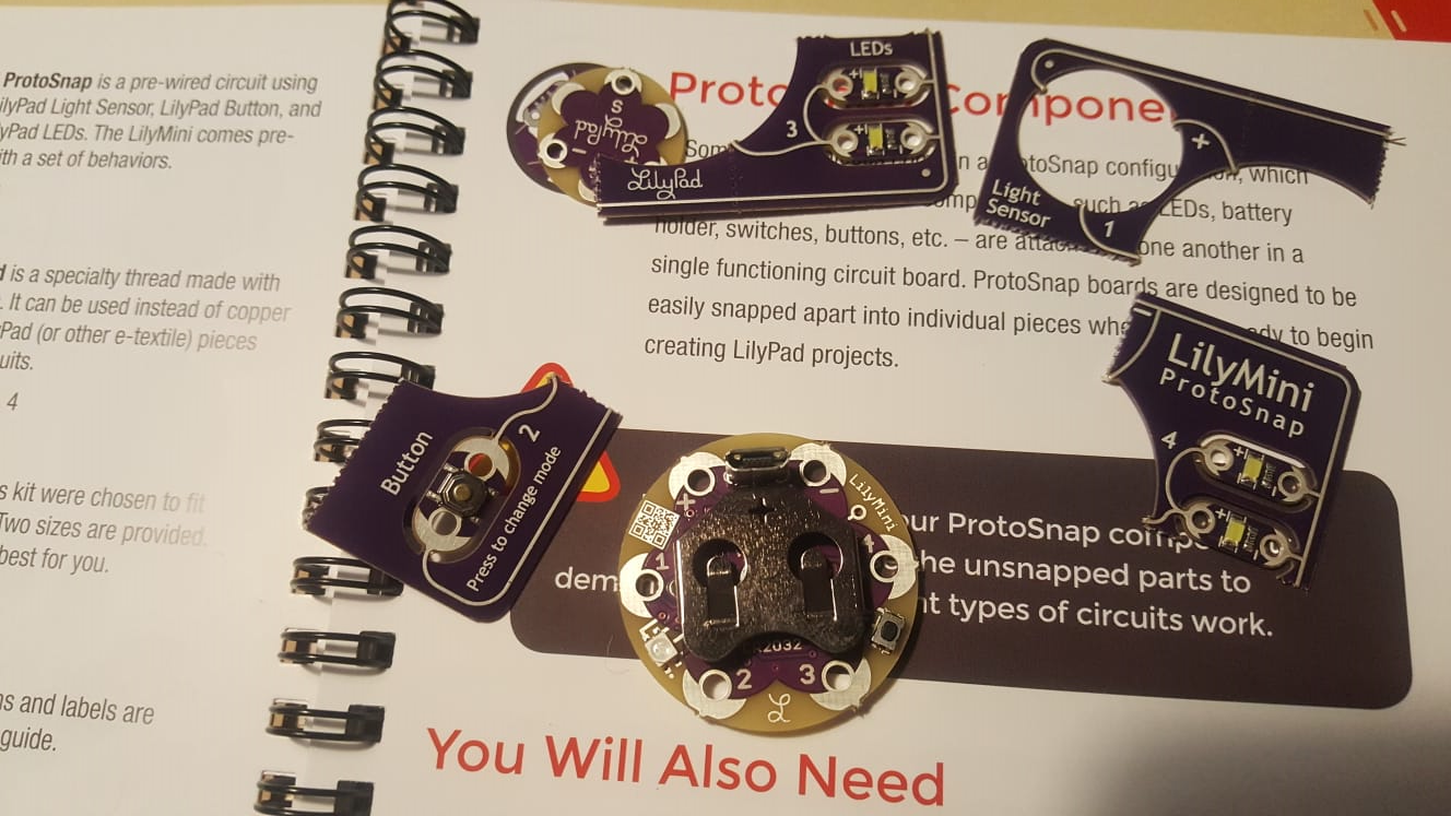
LilyMini ProtoSnap on nimensä mukaisesti Prototypointiin suunniteltu valmis virtapiirilevy. Levyssä kulkevat valkoiset viivat johtavat sähköä. Levyyn upotetun LilyMinin ja muut komponentit voi taittaa varovasti irti. Piiristä löytyvä valosensori on taitettu alla olevassa kuvassa irti levystä.

ProtoSnap on mahdollista purkaa, jolloin voit käyttää LilyMinin portteja monipuolisemmin eri tarkoituksiin. Jos käytössäsi on LilyMini Protosnap, irroita levystä itse LilyMini, neljä lediä ja nappi varovasti taittamalla virtapiirin eri osat irti levystä.

Virtapiiri

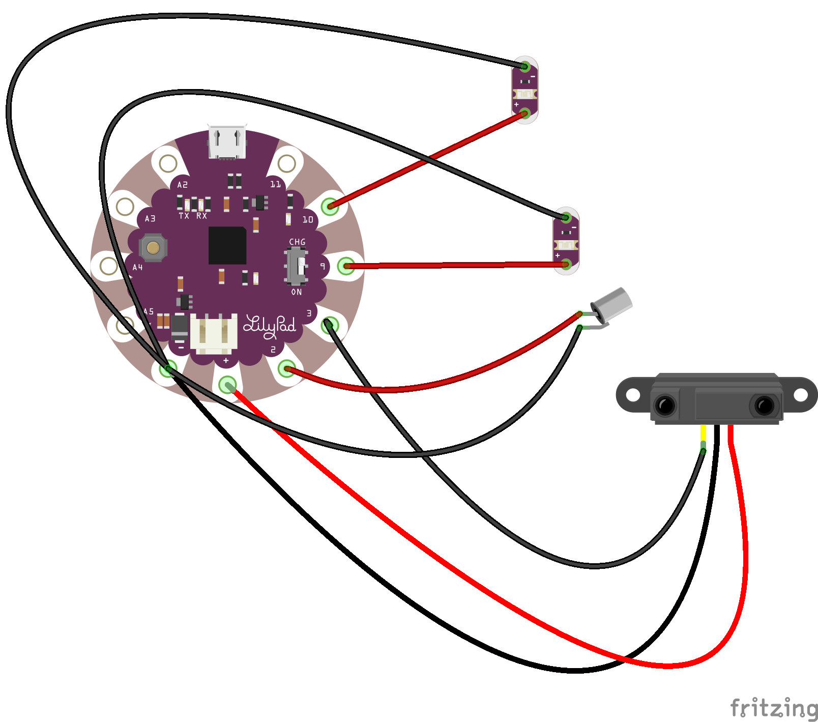
Kun olet purkanut LilyMini ProtoSnapin, voit rakentaa aivan oman virtapiirisi ja ohjelmoida sitä. Löydät LilyMinistä (ja muista LilyPadeista) plusmerkillä merkatun 5V-jänniteportin, miinusmerkillä merkatun maaportin sekä numeroilla merkattuja portteja, joita LilyMinissä on neljä kappaletta (kuvan portit 1-4). LilyMinissä ei ole erikseen analogisia portteja (esim. A0), mutta kaikkia LilyMinin neljää porttia voi käyttää analogisena inputtina, digitaalisena inputtina ja digitaalisina outputtina.

Tee nyt sähköä johtavaa lankaa apunasi käyttäen alla ohjeistettu virtapiiri. Kuvassa näkyy Lilypadin malli, jossa on ProtoSnapia enemmän portteja. Noudata porttinumeroiden suhteen alla olevia tekstimuotoisia ohjeita.

  • Yhdistä ledit portteihin 1 ja 2 sekä maahan.
  • Yhdistä tilt-kytkin porttiin 4 ja maahan. Voit taittaa tilt-kytkimen jalkoja, jotta saat ne solmittua lankaan.
  • Jos haluat, voit kytkeä mukaan myös jonkin analogisen anturin. Kytke anturi porttiin 3, 5V-jännitteeseen ja maahan.

Ohjelmointi 2/2

Kun olet rakentanut virtapiirin, sinun tulisi ohjelmoida LilyMiniä. Tarkista aluksi, että virtapiiri toimii eli että saat luettua tilt-kytkimen ja mahdollisen anturin arvoja Serial Monitorista. Kopioi tätä varten seuraava koodi ja syötä se LilyMinille.

void setup() {
  // Pin 3 is for the distance-sensor and pin 4 for the tilt-twitch.
  pinMode(3, INPUT);
  pinMode(4, INPUT_PULLUP);
  Serial.begin(9600);
}

void loop() {
  //First, print the value from the sensor and then, 
  // the value from tilt-switch
  Serial.println("SENSOR: " + analogRead(3));
  Serial.println("TILT-SWITCH: " + digitalRead(4));
  //Wait for half a second.
  delay(500);
}

Jos arvot ovat outoja, tarkista, että sähköä johtavat langat eivät osu toisiinsa. Kun arvojen lukeminen onnistuu, tulisi sinun seuraavaksi ohjelmoida porttiin yksi kiinnitety ledi syttymään silloin, kun tilt-kytkin sulkeutuu ja porttiin kaksi kiinnitetty ledi syttymään silloin, kun anturin lukema on sopiva.

Tarvitset siis kaksi if-lausetta, joiden tekemiseen löydät ohjeita alta löytyvässä koodissa. Koodi ei ole valmista ja sinun tulee viimeistellä if-lauseet itse.

void setup() {
  // All pins of LilyMini can serve as analog inputs, 
  // digital inputs or digital outputs.
  // Pins 1 and 2 are for leds.
  pinMode(1, OUTPUT);
  pinMode(2, OUTPUT);
  // Pin 3 is for the sensor and pin 4 for the tilt-twitch. 
  pinMode(3, INPUT);
  pinMode(4, INPUT_PULLUP);
  Serial.begin(9600);
}

void loop() {
  //First, save the values of sensors to variables.
  int distance = analogRead(3);
  int tilt = digitalRead(4);
  // Print the value from the distance sensor and then, 
  // the value from the tilt-switch.
  Serial.println("SENSOR: " + distance);
  Serial.println("TILT-SWITCH: " + tilt);
  if(distance > ?){ // Set the right condition yourself!
     // Turn the led in pin 1 on
  }
  else{
    // Turn the led in pin 1 off
  }
    if(tilt == ?){ // Set the right condition yourself!
     // Turn the led in pin 2 on
  }
  else{
    // Turn the led in pin 2 off
  }
}

Mitä seuraavaksi?

Olet harjoitellut LilyMinin käyttöä, mutta prototyypilläsi ei vielä ole varsinaista tarkoitusta. Kiinnitä nyt koko virtapiiri johonkin vaatekappaleeseen ja pohdi, mikä voisi olla hauska käynnistysmekanismi valoille, joko tilt-kytkintä tai sensoria hyödyntäen.

Tutustu aiheeseen lisää hauilla smart fabrics ja e-textiles. Tutustu myös Lilypad Design Kittiin, joka sisältää vaatteisiin ommeltavaa elektroniikkaa. Katso myös Youtubesta videoita näillä hakusanoilla.

LilyMinin mukana tulee paljon vaatteisiin ommeltavia ledejä, jotka hohtavat vain keltaista valoa. Ledeistä saa kuitenkin irti paljon tuunaamalla niitä - esimerkiksi folio ja erilaiset muovit heijastavat ja sirottavat ledien valoja eri tavoilla.