Syventävä: Infrapunaa etsivä auto

Johdanto

Tämä harjoitus on jatkoa neljännen luvun harjoitukselle Syventävä: Infrapunalähetin ja viidennen luvun harjoitukselle Pyörillä ajeleva robotti.

Liikkuva robotti voi liikkua ennalta määritettyä rataa, tai sitten reagoida ulkopuoliseen maailmaan. Tässä harjoituksessa robotti etsii infrapunaa kahden sensorin avulla! Tällainen etsintä tapahtuu haarukoimalla. Jos infrapunaa tulee enemmän oikealta, täytyy auton kääntyä oikealle.

Infrapunaa hyödyntävät esimerkiksi kaukosäätimet. Voit siis ohjata periaatteessa robottiasi vaikka kaukosäätimellä siten, että robotti tulee kaukosäätimen signaalia kohti!

Alla olevassa videossa näytetään, miten kaikenlaisia sähkölaitteita voi käynnistää kaukosäätimestä tulevan infrapunavalon avulla, kun ne on ensin kytketty Arduinoon.

Dejan Nedelkovski: Control any Electronics with a TV Remote | Arduino IR Tutorial

Tekstitykset

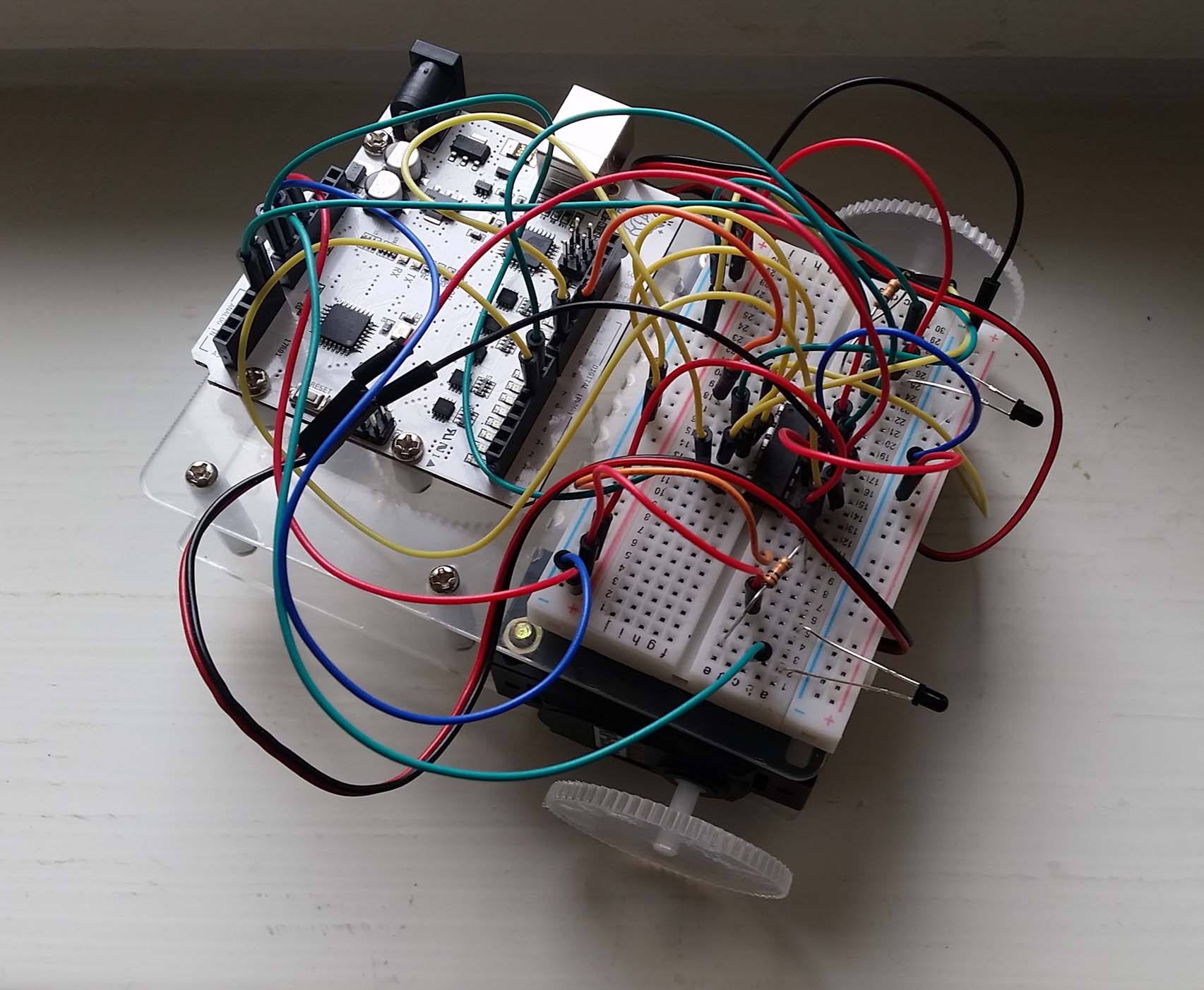
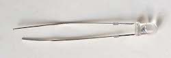
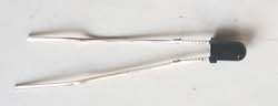
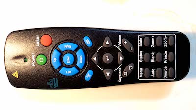
hello Daniel Kottke here from how to mechatronics comm in this tutorial we will learn how to control electronic devices using a TV remote and an Arduino we will make few examples starting from controlling a simple LED then controlling a DC fan speed and controlling high voltage home appliances but first let's explain how it works we can notice that the LED in front of the TV remote flickers when we press a button actually we can only see this through a camera because this is an infrared light and it is not visible to the human eye so the flickering means that when we press a button the infra red LED is sending a burst of light or pulses that we need to receive them with an infrared receiver in this tutorial we will use the V 34 a t-38 IR receiver which has the following block diagram from where we can see that it will amplify filter and then modulate the received signal and provide clean logic output which is acceptable for the digital input of the Arduino board then using the cashiers Arduino IR remote library and it's demo example we can see from the serial monitor a unique hexadecimal code for each button press which we can use it when making our program ok now let's start with the first example controlling an RGB LED so we will control the LED color using the four colored buttons of the TV remote this means that first we need to see the hexadecimal codes for each of these buttons by uploading the IR ref demo example and run the serial monitor we will press each of these buttons and write down their codes now we will modify the demo code like this and add if statements which will be executed if a particular button is pressed so for each button we will set appropriate RGB values and set color function will light up the LED in the particular color for more details how our RGB LED works with arduino visit my arduino RGB tutorial here is the circuit schematic of this example and the source code can be found on my website here's the demonstration the LED lights up with the same color as the pressed button the next example will be controlling a DC fan speed using the forward and backward buttons of the TV remote we will use this circuit schematic for controlling the speed of the fan or actually we will control the PWM signal using the buttons for more details how these circuit schematic works you can check my Arduino motors tutorial here is a quick overview of the source code for this example so using the analog write function we will send PWM signal to the base of the transistor the play button will start the motor at maximum speed or the duty cycle of the PWM signal will be a hundred percent and the stop button will stop it the forward button will increase the speed of the fan with each pressing by increasing the duty cycle of the PWM signal and the backward button will decrease it here's the demonstration of this example the play button starts the motor the backward button decreases the speed of the fan then the forward button increases the speed and the stop button stops the motor the final example will be controlling high-voltage home appliances using the TV remote for that we will need a relay module I will use the HL 52 s relay module which has a rating of 10 amps at 250 and 125 volts ac as we will use high voltage we must be very cautious and I am warning you here that improper or incorrect use could result in serious injuries or death and I don't take any responsibility for your actions for more details how to use the relay and how to make a socket for plugging any electronic device you can check my arduino relay module tutorial here is the circuit schematic for this tutorial with the pin number 7 from the arduino board we will control the relay on which there is a socket for connecting any high voltage electronic device here is the demonstration of this example so using the TV remote we can control any high voltage home appliances thanks for watching and for more tutorials visit my official website how to mechatronics calm

Tarvikkeet

Mehackit boardin (tai Arduinon), USB-johdon, koekytkentälevyn ja johtimien lisäksi tarvitset seuraavat komponentit.

OsaKuvaKuvaus
Pyörillä ajeleva robottiKatso ohjeet robotin kokoamiseen tämän luvun harjoituksesta Pyörillä ajeleva robotti.
InfrapunalähetinInfrapunasäteilyn lähetin. Voit käyttää tämän sijaan myös infrapunasäteilyä lähettävää kaukosäädintä.
Infrapunavastaanotin x 2Infrapunasäteilyn vastaanotin (phototransistor)
Vastus 10 kΩ x 2Vastus vastustaa sähkövirran kulkua. Vastuksen arvo mitataan ohmeissa (Ω) ja ilmoitetaan komponentissa eri värisinä raitoina (tässä ruskea, musta, punainen ja kulta).
KaukosäädinUseimmat kaukosäätimet lähettävät infrapunapulsseista koostuvia sarjoja, jotka vastaanotin (esim. televisio) osaa tulkita ja toimia niiden mukaan.

Virtapiiri

Katso moottoreiden kytkentäohjeet tämän luvun aiemmasta harjoituksesta Pyörillä ajeleva robotti. Alla olevissa virtapiirikaavioissa neuvotaan vain infrapunavastaanottimien kytkentä.

  • Liitä kaksi infrapunavastaanotinta koekytkentälevyn eri päihin kaavion osoittamalla tavalla. Huomaa, että infrapunavastaanottimien pidemmät jalat on kytketty sekä analogiseen porttiin että 10 kilo-ohmin vastuksen kautta maahan. Kaavion alla on valokuva valmiista autosta!
  • Varmista, että et kytke vastaanottimia 6V ulkoiseen jännitteeseen, johon olet kytkenyt moottorit.

Ohjelman tavoite

Robotin kaksi infrapunavastaanotinta lukevat infrapuna-arvoja. Jos arvojen välinen ero on yli 60, tämä tarkoittaa, että infrapunalähetin lähestyy, mutta on joko vasemmalla tai oikealla puolella autoa. Tällöin kokeillaan, kumman anturin havaitsema arvo on suurempi, ja käännetään autoa kyseiseen suuntaan. Jos arvojen välinen ero on alle 60, jatketaan suoraan.

Tarvitset moottoreiden ohjaamiseen käytettävien komentojen lisäksi yhtä uutta komentoa.

Uudet komennot

  • abs(arvo) Palauttaa parametrina annetun arvon itseisarvon, eli etäisyyden nollasta. Käytännössä komento siis muuttaa kaikki negatiiviset luvut positiivisiksi
  • funktioiden luominen ja käyttäminen: Voit luoda omia funktioita, jotka esimerkiksi kääntävät robottia vasemmalle tai oikealle hetken ajan.

Ohjelmointi 1/2

Tehtävä
Syötä alla oleva koodi Arduinollesi. Käynnistä Serial monitor ja liikuttele infrapunalähetintä tai kaukosäädintä auton edessä puolelta toiselle. Minkälaisia arvoja saat? Vastaa lopuksi sivun alalaidassa olevaan monivalintaan ja siirry seuraavalle sivulle.
int rightVal;
int leftVal;
int dif;

void setup() {
  Serial.begin(9600);
}

void loop() {
  rightVal = analogRead(0);
  leftVal = analogRead(1);
  dif = abs(rightVal - leftVal);
  Serial.print("Left Sensor = ");
  Serial.print(leftVal);
  Serial.print("\t");
  Serial.print("Right Sensor = ");
  Serial.print(rightVal);
  Serial.print("\t");
  Serial.print("Difference = ");
  Serial.print(dif); 
  Serial.print("\n"); 
}

Mitä muuttujaan "dif" tallennetaan loop-osassa?

Ohjelmointi 2/2

Tehtävä

Täydennä alla oleva ohjelma ohjeiden mukaan ja syötä se Arduinollesi.

  • Kirjoita moottoreiden määrittelykomennot ja moottoreitasi ohjaavat komennot. Katso apua tämän luvun harjoituksesta Pyörillä ajeleva robotti.
  • Kirjoita arvoja leftVal ja rightVal vertailevat if-osat koodissa olevan if-osan sisään.
  • Kirjoita funktiot turnLeft ja turnRight, jotka kääntävät robottia vasemmalle ja oikealle.
int rightVal;
int leftVal;
int dif;

void setup() {
  // Tähän tarvittavat moottoriporttien määrittelyt.
  Serial.begin(9600);
}

void loop() {
  rightVal = analogRead(0);
  leftVal = analogRead(1);
  dif = abs(rightVal - leftVal);
  Serial.print("Left Sensor = "); 
  Serial.print(leftVal);
  Serial.print("\t");
  Serial.print("Right Sensor = "); 
  Serial.print(rightVal); 
  Serial.print("\t"); 
  Serial.print("Difference = ");
  Serial.print(dif); 
  Serial.print("\n"); 
  if(dif > 60){  
    // Jos rightVal > leftVal, käänny oikealle (kutsu komentoa turnRight).
    // Jos rightVal < leftVal, käänny vasemmalle (kutsu komentoa turnLeft).
  }
  else{
    // Jatka infrapunan etsimistä
  }
}

void turnRight(){
    //Tähän komennot, jotka kääntävät robottia hiukan oikealle.
}

void turnLeftt(){
	//Tähän komennot, jotka kääntävät robottia hiukan vasemmalle.
    
}