Syventävä: Kiihtyvyyden mittaaminen

Johdanto

Kiihtyvyyssensori (accelerometer) on komponentti, joka mittaa nopeuden muutosta eli kiihtyvyyttä. Mehackit Maker kitistä löytyvä komponentti mittaa kiihtyvyyttä kolmiulotteisesti, x-, y-ja z-akseleiden suuntaisesti.

Kiihtyvyyssensori löytyy todella monista arkisista laitteista, kuten uusista puhelimista. Käytännössä kiihtyvyyden mittaamisella voidaan määritellä laitteen asento!

Tässä harjoituksessa pääset tutustumaan kiihtyvyyssensoriin ja tuottamaan sen havaitsemien kiihtyvyyksien avulla erilaisia ääniä.

Afrotechmods: How an accelerometer works!

Tekstitykset

Have you ever wondered how your phone manages to know what direction you are holding it? It's using a device called an accelerometer. It works by sensing the acceleration of gravity and then you can calculate what direction the phone is facing. But how does a piece of electronics sense something mechanical like acceleration? The answer is MEMS. Microelectromechanical systems. MEMS are kind of like silicon integrated circuits but they are mechanical in nature. MEMS manufacturers use similar techniques that are used to make electronics but instead they're making tiny mechanical structures that can interface to electronics... allowing you to build some interesting things. Here I've got some MEMS dies that I made out of silicon. They contain a lot of the same basic structures that you might find in a modern MEMS chip. Let's take a look under the microscope. This is a tiny resistor. The lighter colored material is actually electrically conductive silicon and this darker area that's been etched away doesn't conduct. This long winding electrical path forms a resistor, very similar to how long pieces of wire would also have a significant resistance. So if you made an electrical connection between these two points you'd have a microscopic resistor. Now in order to understand how an accelerometer works, let's look at a MEMS capacitor. It doesn't look like a capacitor does it? Well remember that all a capacitor really is is two conductive plates that are electrically separated. Here are the two terminals of the capacitor. Over here we have what's called a combed finger arrangement. The two structures are very close to each other but they aren't quite touching. Let me highlight it for you. Now it should be more obvious that you have parallel surfaces which form a capacitor. But this is no ordinary capacitor! It's a physical structure that can move. This thing over here is basically a tiny weight made out of silicon and it's kind of like a suspended mass on the end of a spring. Movement, vibrations, and even gravity can cause this little mass to move around and when it does it shifts the entire combed finger structure. When the fingers move the distance between the fingers changes. And when the distance between the fingers changes, you get a change in capacitance. So now we have an electromechanical system that can sense movement and turn it into a changing capacitance value. The next step would be to design circuitry that can sense the change in capacitance and convert it into useful voltages or serial data but that's beyond the scope of this tutorial. A modern MEMS accelerometer will contain structures similar to this except with even more fingers to increase the surface area which increases the capacitance which makes changes in acceleration easier to detect. Here's another electromechanical capacitor except it senses acceleration on the horizontal axis. (Ignore this. That will right buff out.) When the suspended mass moves in the horizontal direction, the surface area between the fingers changes and then you can have some electronics to sense the change in capacitance again. Now if you want to play around with 
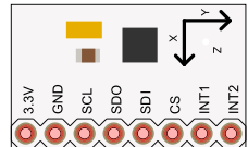
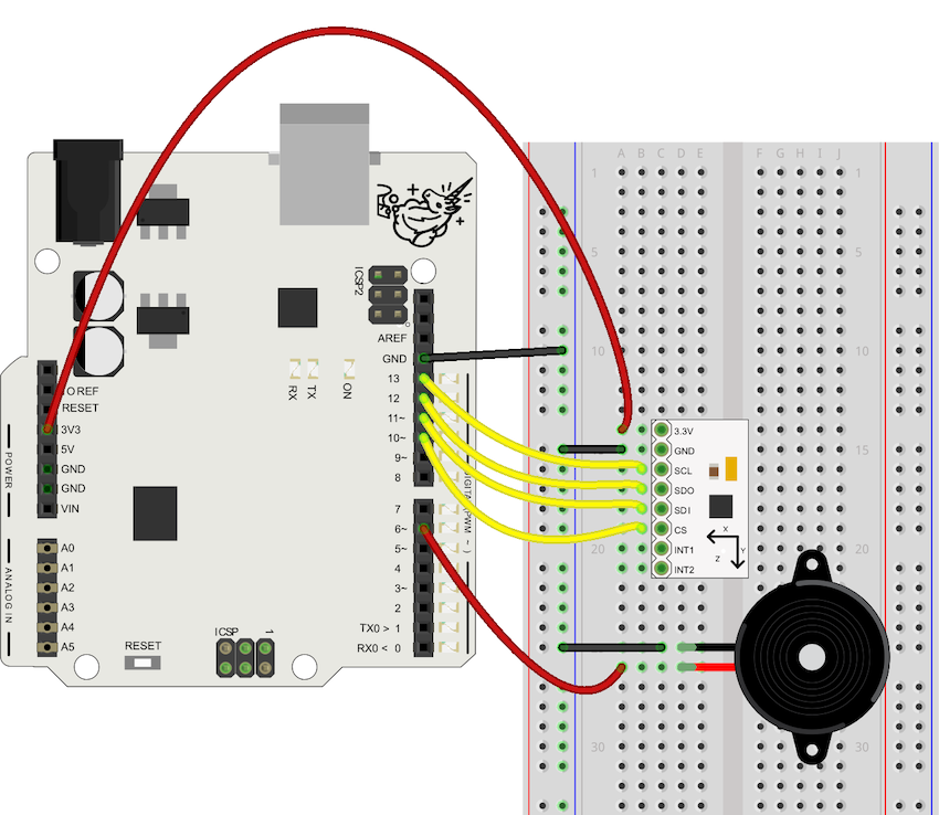
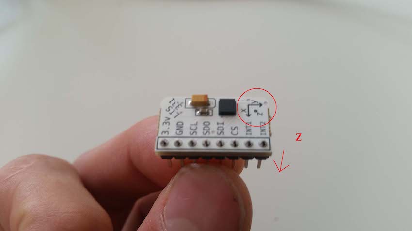
accelerometers at home, you don't need a microscope. You can go to a company like Adafruit and buy a PCB with an accelerometer chip on it. Just power it with 5 volts between Vin and ground and you'll get voltages that correspond to acceleration on the X, Y and Z axes. Now you know how an accelerometer works thanks for watching!

Tarvikkeet

Mehackit boardin (tai Arduinon), USB-johdon, koekytkentälevyn ja johtimien lisäksi tarvitset seuraavat komponentit.

OsaKuvaKuvaus
LIS331 kiihtyvyyssensoriKiihtyvyyssensori rekisteröi x-, y ja z-suuntaisia kiihtyvyyksiä ja sen kanssa voi viestiä esimerkiksi SPI-kommunikaation avulla.
Piezo-kaiutinElektroninen komponentti, jota voi käyttää värähtelyn havaitsemiseen sekä äänten tuottamiseen.

Virtapiiri

  • Yhdistä kiihtyvyyssensori kuvan mukaisesti 3,3 voltin jännitteeseen, maahan ja portteihin 10, 11, 12 ja 13.
  • Yhdistä piezo-summeri digitaaliseen porttiin ja maahan.
HUOM!
Älä yhdistä kiihtyvyyssensoria 5V -jännitteeseen, sillä se voi rikkoa sen!

Ohjelmointi

Löydät kiihtyvyyssensorin käyttämiseen tarkoitetun ohjelman täältä. Ohjelma on melko pitkä ja hieman monimutkainen. Lukemalla ohjelmaan kirjoitetut kommentit saat kuitenkin hyvän yleiskuvan siitä, miten ohjelma toimii.

Tehtävä
Kopioi ohjelma linkin takaa ja syötä se Arduinollesi. Avaa Serial monitor. Kääntele kiihtyvyyssensoria ensin paikallaan. Kokeile tämän jälkeen heilauttaa sensoria kiihtyvällä liikkeellä eri suuntiin. Mitkä ovat suurimpia arvoja, jotka sensorista saat x-, y- ja z-suuntaan? Osaatko sanoa, mitä yksikköä arvot edustavat?

Arvot on muunnettu putoamiskiihtyvyyksiksi (g = 9,81 m/s^2). Arvo 2 tarkoittaa siis kahta putoamiskiihtyvyyttä. Kun pidät sensoria paikallaan, alaspäin suuntautuvan kiihtyvyyden pitäisi periaatteessa olla painovoimasta johtuen yksi putoamiskiihtyvyys. Kun sensori on vaakatasossa, z-akseli osoittaa alaspäin.


Mihin seuraavista käyttötarkoituksista kiihtyvyyssensori parhaiten sopii?

Taikasauvan tekeminen

Kytkit aiemmin mukaan myös piezo-summerin. Nyt sinun tulisi tehdä ohjelma, joka soittaa säveliä kiihtyvyyksistä riippuen!

Tehtävä
Poista kommentointimerkit ("//") riviltä 36, jossa kutsutaan funktiota magicWand eli toisin sanoen ota rivin 36 komento käyttöön! Heiluta kiihtyvyyssensoria ja tarkkaile, minkälaista ääntä piezo tuottaa.
Tehtävä
Muokkaa magicWand -funktiota ja katso, minkälaisella logiikalla äänet olisivat mahdollisimman mielenkiintoisia. Saatko piezon soittamaan erilaisen äänen aina silloin, kun kiihtyvyys x-, y- ja z-suuntaan ylittää arvon 2?

Huomaa, että aina tasaisessa liikkeessä kiihtyvyys on 0, joten ääntä ei silloin periaatteessa kuulu. Saat ääntä ulos vain kiihtyvässä liikkeessä! Koska painovoima kuitenkin tuottaa sensorille koko ajan pientä kiihtyvyyttä, niin piezo pitää “normaalitilassakin” matalaa ääntä.

Alla on video esimerkkitaikasauvasta! Voit tehdä omasi tai kehitellä ideaa eteenpäin osana kurssin loppuprojektia.

Mehackit: Magic wand

Lisätietoa

SPI-kommunikaatio?

Kiihtyvyyssensorin kanssa viestitään SPI-protokollaa käyttäen. Arduino lähettää viesteinä kahdeksan bitin tyhjiä tavuja (bytes) kiihtyvyyssensorille, joka vastaa lähettämällä tavuja takaisin. Kiihtyvyyssensorin takaisin lähettämät tavut ovat kiihtyvyyssensorin havaitsemia x-, y- ja z-suuntaisia kiihtyvyyksiä. Koska monipuolista dataa vaihdetaan paljon, täytyy viestinnän olla selkeää ja tarkasti ajastettu. Ajasta pidetään kirjaa kiihtyvyyssensorin SCL-portin kautta, jonka kytkettiin Arduinon porttiin 12.

Lisätietoa SPI-kommunikaatiosta