Hack Your Toy

Introduction

You’ve learned how to turn different things on and off with varying methods - magnets, touching, and tilting. Things you’ve turned on so far have been parts of your Maker Kit, such as LEDs and motors. But what if you wanted to turn on some external device, such as an electronic toy? In this project, we’ll do just that!

Electronic devices usually have their own power supply, e.g., a battery. That’s why we’ll sort of divide the circuit in two. Arduino will use its power supply, and the toy its own. You’ll need a transistor for that.

For this exercise, you’ll need an electronic toy. The toy has to work, and you must be able to take it apart so that you can get your hands on the two wires (ground and voltage wires) coming from its power supply. Below is a video of the Mehackit Dino, which is turned on with the help of a microphone by clapping your hands! What kind of mechanism would you like to use to turn your toy on?

Toy hacking - Dino


Parts

In addition to Arduino, the USB cable, breadboard, and wires, you’ll need:

PartImageDescription
NPN transistor

You have three of these in your Maker Kit. Make sure that the component has MP5 written on it, not TMP (like in the temperature sensor) or FT66T (like in the melody generator).

Diode

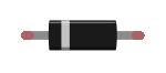
In this exercise, the diode is used to make sure that possible surges don't move from the toy's power supply to Arduino. The diode allows current to flow toward the striped end, but not the other way

An electronic toy to hack

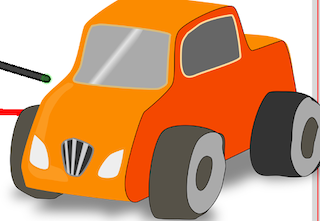
The toy must work and be relatively easy to take apart so that you can find the two wires going into the power supply.

Wire cutters For cutting and peeling the toy's wires.
Soldering ironThis is not essential, but it will make your job easier! Ask your instructor if they could arrange you one for some of the classes.
Screwdriver

For taking the toy apart. You can find a small Phillips screwdriver with a black handle in your Maker Kit. If there are other screws in the toy, ask your instructor for help!

Resistor 1 kΩ

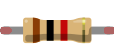
The resistor resists the flow of electric current. The value of the resistor is measured in ohms (Ω) and announced in the component in stripes of different colors (in this case brown, black, red and gold)

Reed switch
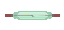
Closes the circuit when a magnet is brought close to it
Resistor 330 Ω
LED 

The longer leg (the one with the bend in the picture), i.e., anode to the + -terminal, i.e., to Arduino's pin. The shorter leg, i.e., cathode to minus-terminal, i.e., ground.

Circuit

The first aim is to turn on the LED with a transistor. Later, we’ll replace the LED with an electronic toy, which you can turn on with the same logic.

Note, that the LED isn’t connected to Arduino’s digital pin, so you can’t directly use it through Arduino! This time, you’ll control the LED through the transistor.

  • Connect the longer leg of the LED through a 330-ohm resistor to Arduino’s 5V voltage and the shorter leg to the transistor’s leg that is on the right side.
  • Connect the middle leg of the transistor through a 1000-ohm resistor to pin 6.
  • Connect the left leg of the transistor to ground.

The Aim of the Program

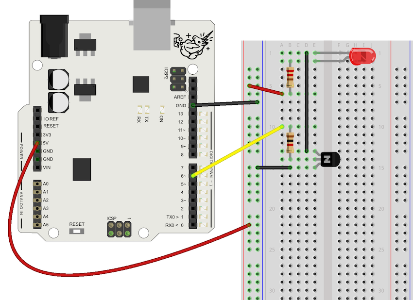
When the switch is closed, the middle leg of the transistor receives voltage from pin 6. Now, the transistor connects the other two legs and the LED’s (and later the toy’s) circuit closes. When the switch is not closed, the transistor receives no voltage, the LED’s circuit disconnects and the LED isn’t on.

Necessary Commands

Programming 1/2 - Testing with the LED

The aim is to first try if you can use the LED through the transistor. Later, we’ll replace the LED with the electronic toy!

Task
Copy the code in your Arduino. Then answer the quiz at the bottom of the page.
void setup() {
  pinMode(6, OUTPUT);
}

void loop() {
  digitalWrite(6, HIGH);
  delay(4000);
  digitalWrite(6, LOW);
  delay(4000);
}

What happens, when you apply voltage through pin 6 to the transistor's middle leg with the command digitalWrite(6, HIGH)?

Finding the Toy’s Power Supply

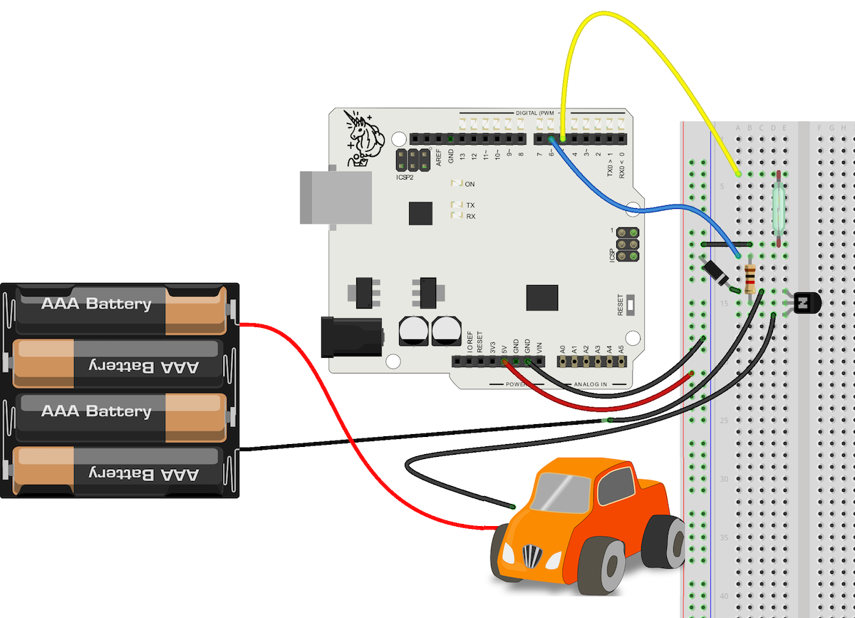
With the instructions above, you turned the LED on and off by using Arduino. Next, you’ll turn on the toy instead of the LED. The legs of the LED are simply replaced by the two wires of the toy!

IMPORTANT!
For electrical safety reasons, the maximum supply voltage of your toy must not exceed 6 V. Remove the power supply from the toy while you are tinkering with it!
Task
First, you have to find the toy’s power supply. To achieve that, you’ll need to find the grounding and voltage wires going to the power supply. They run inside the toy, so you’re going to have to take it apart! Below are some instructions. Each toy is a little bit different, which makes it impossible to give specific instructions. That’s why it’s important to ask your instructor for help!
  1. Make sure your toy works! If the toy is old, the batteries may have run out. In that case, change the batteries and check again. When you’re done, remove the batteries.
  2. You should get your hands on the two wires coming from the toy’s power supply running inside the toy. The power supply is often under or at the back of the toy, which is why you’ll need to take the toy apart a bit reach them. Start the disassembly by removing the outer casing of the toy (this may require some unscrewing). This way you’ll get a look inside the toy.
  3. Open the other screws as much as you need to find the wires going to the toy’s power supply. If you’re hacking a plush toy, you may need to pull out the toy’s stuffing to find the wires.
  4. Use the wire cutters to cut the grounding wire (it’s often black) approximately in half.
  5. Put the batteries back in. The toy won’t start because the circuit is not closed. Connect the ends of the grounding wire. The toy should start.
  6. Now you can move to the next tab, where we’ll replace the LED with the toy!

Connecting the Toy

Task

For safety reasons, make sure the batteries are not connected to the toy during the next phase.

Disconnect the LED from the circuit and replace it with the electronic toy according to the schematic below. Also, connect the reed switch to the circuit.

Just like before, applying voltage to the middle leg of the transistor connects the other two legs. Connect the two ends of the grounding wire you cut to the left and right leg of the transistor.

Note!
If the toy’s wires are too short or thin, it can be tricky to connect them to the breadboard. In both cases, the wires need to be extended for them to reach the breadboard and stay attached to its holes. You may need a soldering iron for that. Ask your instructor for help.
  • Connect the reed switch to pin 5 and to ground.
  • Connect the middle leg of the transistor through a 1000-ohm resistor to pin 6.
  • Connect the grounding wire of the toy’s power supply to the left leg of the transistor. Connect this leg to Arduino’s ground as well.
  • Connect the grounding wire going to the toy to the right leg of the transistor. Also, connect the right leg through the diode to Arduino’s ground. Make sure that the stripe in the transistor is pointing towards the transistor! That way, current flows to the transistor, but not the other way round.

Programming 2/2 - Controlling the Toy

Task
Complete the program and upload it to your Arduino.
void setup() {
 //Set the state of the reed switch to INPUT_PULLUP
 //Set the pin of the transistor to  OUTPUT
}

void loop() {
  //If the reed switch closes, apply voltage to the transistor and start the toy
}

Which of the following can you connect to Arduino?

Further Development

When you’re able to start the toy with the transistor, you can develop your project further in many ways. Here are two options!

Testing different switches and building chain reactions

Previously, you turned on the toy with a magnet using a reed switch. How else could you start the toy? Could a magnet tied to a string swing next to the reed switch, which starts the toy, which topples a glass of water, which closes the next switch and starts something else… Use your imagination!

Circuit bending

Circuit bending means modifying the toy’s circuit. So far the only alteration you’ve made was cutting one wire. You could, for example, modify the toy’s sounds by adding a variable resistor in a convenient place in the circuit. Below is a video introducing you to the world of circuit bending!

chewy01234: Basic circuit bending tutorial

Transcript

[Music] [Applause] hello and welcome to my second method first we will take a look at the tools that we need to get started we have a screwdriver some alligator clips a solder and the soldering iron wires and a wire stripper three components a button to switch and a potentiometer and last but not least a drill let's unscrew our toy and open it up be sure you save all your screws as you'll probably want to put your toy back together once you're all done gently open up the toy and expose the circuit board underneath now we're going to take a look and search for some possible Bend spots take your alligator clips and just poke around anywhere word of warning make sure you stay away from anything connect into the batteries as you may hurt yourself or break your toy once you have the green part of the circuit board exposed with all the little solder points you're going to take your alligator clips and just start poking around you might want to activate a sound first so there's something playing and then go to town [Music] [Applause] [Music] there's been that particularly it adds a funky drum rhythm the back with the side I like that let's solder it up and make it permanent [Applause] after you've marked the two points that you made a connection with you're going to solder a wire directly to one of the points [Music] then you're going to solder another wire to the other point make sure they're on there nice and tight next we're going to solder to our component I chose a switch but you could use a button or potentiometer or really any other connecting component you can think of a switch is the best for our situation currently so once you got that on there nice we're going to drill into the case and mount the switch right on today so pick a nice spot that's open that's much going on around it and make sure also that you leave enough room on the inside where you'll be able to close everything back up take that screw hook it right through the hole and attach the bolt right back onto the top of it and hold it in place now once you got everything closed back up we're going to give it a final test let's see how it works [Music] [Applause]