Watering Plants with Zero Effort

Educator notes

Educator Intro

This project is a great opportunity to combine handicraft skills with creative coding! It’s advisable that before starting this project, your students and yourself are all ready familiar with the Electronics & Programming Basics. Nevertheless, the difficulty of this project is easy.

You can find the full code for the project here.


Key concepts for this project

  • Implementing ideas into projects
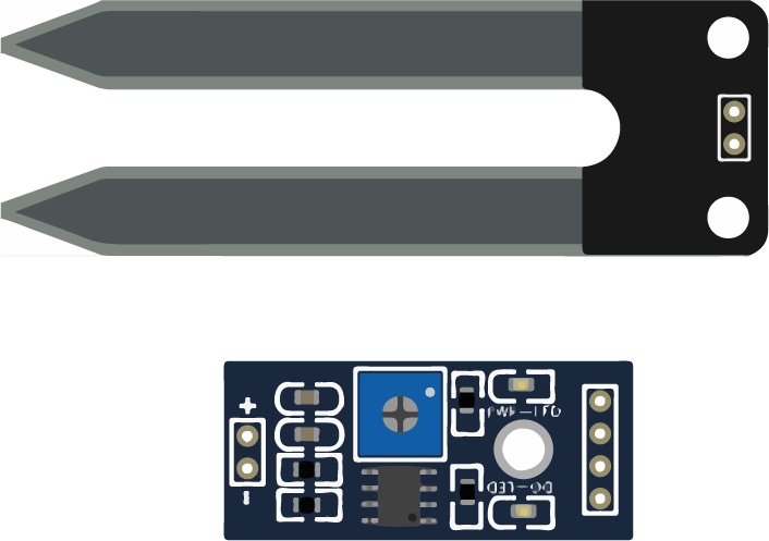
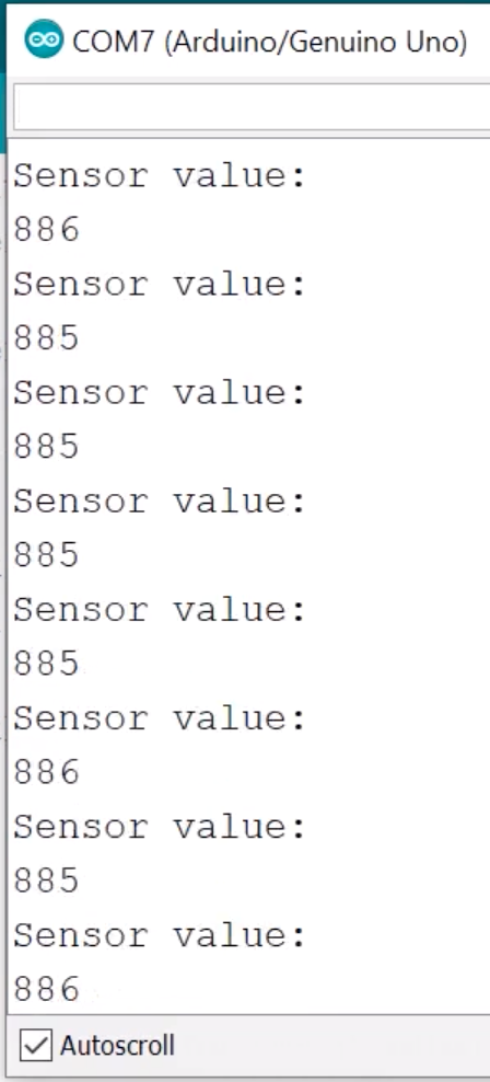
  • Mesuring moisture with Arduino
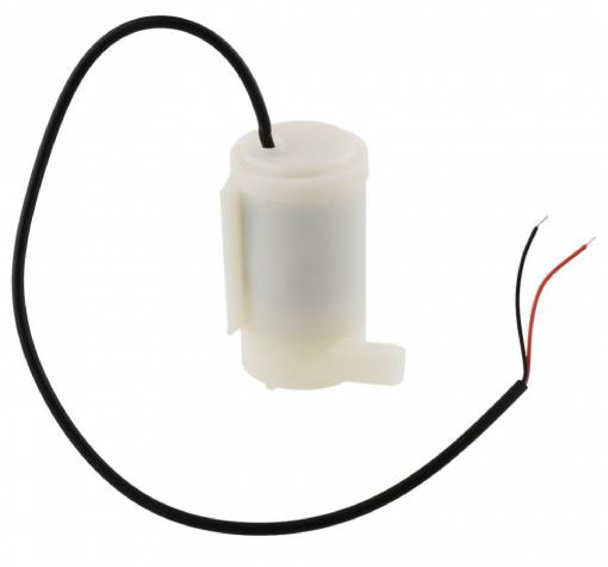
  • Controlling motors with Arduino
  • Editing / calling external functions
  • Controlling time with Arduino.

Learning Objectives

The student…

  • …can implement previous knowledge acquired from the Basics-module.
  • …can create and call external functions.
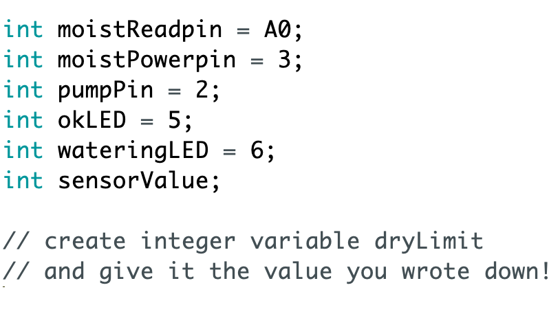
  • …can tweak the code to obtain more precise results.
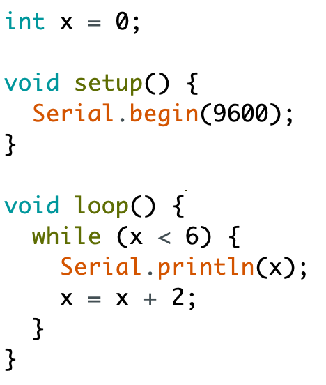
  • …can execute code at specified intervals.
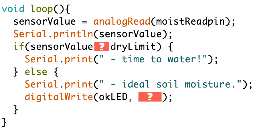
  • …can control a simple water pump with Arduino.
  • …understands how different moisture-sensors work.

Introduction


What triggers the water pump to work in this automatic plant irrigation system?

Parts

Transcript

It's time to start building your watering system. You can use quite a few things you already have at home plus an Arduino and some components. You'll need an Arduino or a Mehackit board, USB cable and a breadboard, and if you have a power supply for the board it will be practical, later on. You'll need wires and electric tape, a moisture sensor, I will use the one included in the maker kit: YL69. A water pump, a small one, a 9-volt battery and a battery snap, two LEDs: yellow and green for example, a transistor, a diode, two 330 ohm or 220 ohm resistors, a 1 kilo-ohm resistor, nice extra but not critical: two terminal blocks. A glass jar, a plastic tube for the water - should fit the pipe of the pump. You can extend those tubes, too if needed. And yeah, a plant. It should be pretty dry to start with. There are different moisture sensors available. If you don't have a sensor you can actually make one yourself. Check the extras to find out more about moisture sensors and how to make and connect them. The sensor you'll use measures how well electric current flows between one pin and the other. There is only current if there's something that conducts electricity between those pins. Dry soil doesn't conduct electricity well at all, it has a big resistance. But wet soil conducts well. This means, if your sensor readings show, that the soil resists current a lot, you need to water it. Here's how the watering system will look like in the end. Cool! Go ahead and check you have all that you need.

Do this

Find a house plant with DRY soil! Don't choose a cactus. You'll also need a glass jar or similar for water.

Collect these components. In addition to them you will need an Arduino UNO or Mehackit Board, a USB cable, a breadboard and a bunch of jumper wires.

PartImageDescription
Moisture sensor + controller board (YL-69, FC-28 or similar)The moisture sensor we're using is resistive. It measures the resistance between the sensor pins. The sensor must be connected to a controller board which comes with it. The other type of moisture sensor is called capacitive - it may work as well in this project. If you're using one, test it and tell us how it went!
Water pump + silicon tube

Small water pumps contain a DC motor. Water gets sucked in through the hole in the bottom of the pump, because a fan rotates inside the pump. The water comes out through the small tube on the side. Never connect a pump directly to an Arduino: you'll need a transistor or a relay for that.

The tube is needed for leading the water from the pump to the soil.

9V battery + battery snapThe battery will power up the pump only.
Transistor 2N2222A transistor is used to switch the water pump on and off safely. There are different kinds of transistors - here you'll need a so-called NPN transistor, like model 2N2222 we're recommending.
DiodeA diode is used here to stop current spikes from flowing back from the water pump. Current spikes may damage other components in your circuit.
2 x LEDLEDs are needed for indicating what's going on with the watering system. Green: soil is ok - Yellow: watering in process
2 x 330Ω or 220Ω resistorThese resistors will protect the Arduino pins you connect the LEDs to.
1 kilo-ohm resistorThe current from a digital pin to the base pin of the transistor must be limited with a 1kΩ resistor. Stripe colors: brown, black, red, gold.
Extension wires + electric tapeFemale-female extension wires will help you place the pump, the moisture sensor and the Arduino where you want. Use electric tape (or similar) to connect the wires so they don't come off.
OPTIONAL: 2 x terminal blockTerminal blocks make it easier to connect things to the breadboard. You can use them to extend wires, too.

How does the YL-69 moisture sensor work?

Let’s Wire It 1/2

Transcript

It's circuit time! The first component that you will connect is the moisture sensor. As you can see the moisture sensor looks a little bit like a horseshoe. There are two pins and on top of it two connectors. These two must be connected to a controller board with two jumper wires. Next you'll need three extension wires. Connect them to the controller board pins named AO - that's analog output, GND as you already know means ground, and VCC. That's where the sensor gets power. There's one more pin on the controller board: it says DO. We don't want to use that one. It's the digital output. You would get only ones and zeros from that pin. So AO, analog output, is much better. Continue these three wires with normal ones, the longer the better. Let's see. The AO wire goes to the analog pin A0 on the Arduino. GND to a GND pin and finally, connect the VCC from the controller board to the 5V pin. Next up, the transistor. This one we'll use as a switch for the water pump. You can program it to turn the pump on and off. Attention: make sure you connect every pin correctly or the transistor might break or heat up. Check this out: the flat part of the transistor is facing the Arduino board. The transistor has three legs with funny names: emitter base and collector. I'm not going to explain all about transistors right now but just make sure you get the pin order right. Connect a 1 kilo-ohm resistor to the leg in the middle, the base. From there connect to the digital pin 2 on the board. Then connect this one, the emitter, to the GND line in your breadboard. A jumper wire goes from that line to a GND pin. The next component is the diode. You have to be careful when connecting motors because they can create current spikes that can damage the Arduino. A diode only conducts electricity to one direction so you can use it to block such current spikes. Well, at least if you connect it the right way. The gray stripe here shows which way you need to connect it. This way the diode blocks current, this way it lets current through. Connect the black side of the diode to the collector of the transistor. Put it close to the transistor pin because more stuff needs to fit here later on. The gray side of the diode goes to just some row that's free. Go ahead and connect all that and then we can add the water pump.

Do this

Make a circuit according to the diagram below.

Connect the moisture sensor to the control board.

Connect the control board pin AO to A0 on the Arduino, GND to GND and VCC to 5V.

Note: the order of these pins may vary on different sensors!

Put the transistor on the breadboard flat side towards the Arduino. Connect:

  • top pin (emitter) to GND through the side row
  • center pin (base) to pin 2 through a 1kΩ resistor
  • a diode to the bottom pin (collector). The other pin of the diode goes to an empty row. Make sure the diode is connected the right way: the gray band away from the collector pin of the transistor.

Why do you need a transistor in this project?

Let’s Wire It 2/2

Transcript

Let's connect the water pump. The pump isn't too complex. Inside it there's a DC motor that spins this way or that, depending on how you plug it. At the end of the motor you have a propeller which looks like a fan. If you look at the pump there's a hole in the bottom. The water gets sucked through it and then the propeller sends it to the exit hole that's the short pipe here. First connect a tube to the pipe. It has to be long enough to go from the pump all the way to your plant. If you have a terminal block connect it to the wires of the pump. This way it's easier to connect extension wires. You can also tape or solder the extension wires to place. Use electrical tape for this. It's a good idea to use pretty long extension wires. Now connect the wires to both sides of the diode. Over here it's important that the order is the following: collector pin of the transistor - diode - water pump wire. The water pump is now connected! The pump needs a higher voltage than the Arduino can deliver. That's why you need a 9-volt battery. The battery will only be used to power up the water pump. Again you can use a terminal block or electric tape to make these wires a bit longer. Be careful with the battery and don't let the wire ends touch or it will heat up. Connect the battery to the long row on the side like this: black wire to the ground and from this row continue to the motor over here. Almost done. Now you just need some sort of a signal to see how your plant is doing. Let's say a green LED will mean that the soil is watered and the plant is fine, and yellow LED turns on when the soil is too dry and the water pump is starting to pump. And that's it, everything's wired and ready. Bye! No, oh no, that's not all, is it. Now it's time to code the whole thing.

Do this

EXTEND THE WIRES OF THE WATER PUMP, IF YOU CAN! USE A TERMINAL BLOCK IF YOU HAVE ONE, AND EXTENSION WIRES. SECURE CONNECTIONS WITH ELECTRICAL TAPE OR BY SOLDERING.

Finish the circuit according to the diagram below.

  • Connect the water pump (motor in the diagram): put the pump wires on both sides of the diode. Note the order of pins and wires on the diagram!
  • Connect the 9V battery to side rows: negative terminal to GND row, positive terminal to a red row on the side.
  • Connect a wire from the red side row to the motor

Why can't you connect the water pump directly to a digital pin (0-13)?

Test the System

Transcript

There's quite a few parts in the system so we'd better make sure everything works. Let's test the most important parts: the moisture sensor, the water pump and the LEDs. First just stick the moisture sensor in the soil. At this point the soil should be dry. Push the sensor until the metal sheets on the pins are three-quarters inside the soil. Don't stick it too deep: the readings may get weird and the sensor might even break. Now place the pump inside the water jar and put the end of the tube into the soil, close to the moisture sensor, let's say 5cm away from it. The position of the pump matters. The water jar shouldn't be above the plant. If it's too high what happens is this: when the pump is first turned on the water will just keep flowing and flowing, even when the pump stops. Fun fact: this is called the siphon effect. Too much water could damage the sensor and the plant. Check that the extension wires of the pump don't touch water. The connection you made is not waterproof. The components and materials you have at hand may be a bit different than mine so the pump might look a bit different and the wires may not be quite the same. That's why you should check the safety instructions of the components you have before you power the whole thing up. Now let's run a test program to see everything's working. Open the Arduino IDE, save the program and give it a name. Go to File > Save as... > Plant project. Delete all the text from the programming window. Now follow the link under this video, copy the code from the page it leads to and paste it into Arduino IDE. I'll explain later what this code does. Remember, the soil of your plant should be dry. Try it with your fingers and find another plant if it's too moist. At this phase you will define the sensor values for dry soil which is ready for watering, and the values when the soil is wet enough. Upload the code to your Arduino board and open the serial monitor. First there's the LED test: the two LEDs should turn on and then turn off. Second the pump test. You'll hear the pump working for a moment. Maybe even some water comes out, depends on the length of the tube. The third test checks the sensor. The program takes 200 readings from the moisture sensor and prints them in the serial monitor. My sensor, YL69, takes a while to stabilize after it has been powered up. The time it takes to settle may vary with other sensors. Check the numbers on the serial monitor. You should see the numbers settle towards the end. Write down the value which seems to be the final one, you'll need it later. If the LEDs and the pump turned on and you got readings from the sensor, everything's working. Congratulations! If something went wrong don't worry. Check your circuit and repeat the test. You can run tests as many times as needed. To run the test again press the reset button on your board or just close the serial monitor window and open it again. When everything seems to be in order it's time to do some actual measurements.

Do this

The sensor and the pump

  • Check the soil: it should be pretty dry!
  • Put the sensor into the soil: 3/4 of the sensor pins should be covered.
  • Put the tube of the water pump near the sensor. You can use a paper clip to keep the tube in place.
  • Put the pump into the water. Only put the insulated part of the pump into the water - NOT the joint where you've  connected the extension wires!

The code

The tests

  • Upload the code to the Arduino and open the serial monitor
  • Look at the sensor numbers in the serial monitor: towards the end they should stabilize. 
  • Write down the number that looks like the final one.\

If the serial monitor looked like this in the end, you could choose either 885 or 886 and write that down.

  • Did the LEDs light up and did the pump activate? If you're not sure, repeat the test by pressing the reset button of the Arduino or by closing and opening the serial monitor.
  • If something doesn't work, check the circuit and repeat the test.


You checked the sensor values in the serial monitor and wrote down the value that seems to be the final one. What value did you write down?

What’s in the Test Code?


Do this
Read the code you copied carefully!

Why is it a good practice to make functions outside the loop and setup parts for some of the code?

Measuring the Soil Moisture

Transcript

Now it's time to read some sensor data from the soil. Remember, to do this you need a plant with dry soil and a sensor that's stuck in it. And by the way, don't use a cactus. I think a plant that can be watered pretty often is good for this project. In the previous phase I asked you to write down the value you get in the end of the tests. If you need to check it again just close the serial monitor, open it and wait a little bit. Let's use that value to define a new integer variable. I'll call it dryLimit. The value is the number you wrote down. Your dry limit is probably a bit different than mine and it's okay. Now let's move on to the loop part. That's where you need to read the moisture sensor value and you store it to sensorValue variable. The command for reading the sensor value is a familiar one: analogRead. The sensor is connected to a pin which is defined here, remember? It's moistReadpin, A0. I'll check quickly what's the difference between wet and dry with this sensor. When the sensor is in water, the values go down. And when it's in dry air the value is as big as it can get: 1023. Air doesn't conduct electricity at all. If the sensor values go bigger than the dry limit you defined, it means the soil is too dry. If the soil is too dry, the water pump should start pumping. Else, if everything is just fine, the pump should be off. Sounds like you need an if-else statement in your code. Here's how it will look like. There are a couple of things here you need to figure out yourself. What's the correct operator to compare the sensorValue and the dryLimit? In the end there's also the good old digitalWrite command. When the plant is okay it should turn the green LED on to show you everything is fine. Hmm but there's something missing. I'm sure you know what to write there to make the LED light up. So go ahead and write that code. Fix the if statement and the digitalWrite command. You can also upload the code if you want. After that we'll make the water pump work

Do this

Go to the beginning of the code and create a new variable dryLimit.

  • Give it the value you wrote down.
  • Go to the loop part and write the code below.
  • Fill in the missing parts that are marked with a question mark!

You can upload the code to the Arduino, too.


What kind of values do you get from the moisture sensor when the soil is dry?
If you upload this program to the Arduino, it runs the tests first. What happens after that?

Water Pump

Transcript

So, your next step is making that water pump work. You'll write a new function down here for that. I'll call it water(). Putting all the commands that control the pump inside a new function will keep your code clear. If you look at the loop part it should be easy to understand what the code is supposed to do. There shouldn't be too much stuff. From the loop part you can call functions you've written yourself by using their names. If I write water(); inside the if statement Arduino will run all the commands inside water() function when - let's see, when the soil is too dry. Now let's finish the water() function. What should it do? It should power up the water pump so the plant gets some water. This command will turn on the pin that the transistor is connected to. What happens is the transistor will then let an electric current from the battery to pass on to the pump and it will start working. Woohoo! You have to define the time the pump must be on and that you can do with the delay command. First, turn the pump on, then wait for a while, then turn it off. The length of the delay really depends on how long the tube is. The pump turns on, it takes a while for the water to go through the tube and then it goes to the soil. Start with 500 milliseconds, half a second, that is, and make it longer if the water never comes out of the tube. If the time is too long the plant will be flooded so you really need to test a bit and change the timing. After this it's your task to write the command to turn the pump off, too. And a final thing: let's turn the yellow LED on here, too, so you can see when the pump is working from a distance. Also, turn the LED off when watering is finished. Congratulations, you are now halfway there with the project. There are just a few little steps to go.

Do this
Develop the code as instructed in the video.

If you upload this code, it will run the tests first. When does the yellow LED turn on, after that?

Save the Sensor

Transcript

Let's recap what you have until now. You ran tests to see everything works. You're printing values from the moisture sensor, and you've coded the pump to work when the soil is dry. And you have signal lights to show what's happening. Isn't that enough already? Well, sure: the watering system is working now. Here at Mehackit lab we test always these projects, and while testing this one we noticed something nasty happens to the sensor if you use it like this. It's all corroded! What happened! This one was in the soil for only a week and it's destroyed. When the sensor is connected there's a current passing from one metal surface to the other all the time. In soil, which is moist. And that leads to corrosion pretty fast. How to fix this? We started thinking, does the sensor really need to be on all the time? Wouldn't it be enough if it checks the soil moisture every now and then? Sounds good. We'll program the sensor to turn off for let's say 10 minutes, and this will both save energy and save the sensor. But how can you program the sensor to turn on and off? It's connected to a constant voltage from the 5V pin. Aha, instead of 5V you can connect it to a digital pin which you can program, pin 3 for example. These pins deliver 5 volts too but you can program them on and off. Before connecting to pin 3 I checked the datasheet of this sensor and learned that the maximum current it will ever draw from a pin is 35 milliamperes. So, if your sensor is different from mine, you should maybe make sure that it doesn't require more than 40mA of current. That's the maximum these digital pins can handle. You need to change the code too to make this work. First, create a new integer variable: moistPowerpin and give it the value 3. That's the pin number. Then go to setup and define pin 3 as an output. Leave the rest of the code as it is. But change the runTests() function a little bit. In the beginning of the sensor tests, turn on moistPowerpin - just before the test measurements. Turn it off after the tests are done. You can upload the code now and run the tests. Those should work. And the next thing will be fixing the main code.

Do this
Check what kind of a moisture-sensor you have. Develop the code as instructed in the video.

What will prevent the sensor from corroding?

Code a Rest Cycle

Transcript

When you turn on pin 3, which is the power pin for the sensor, it can measure. When you turn the pin off it won't do anything. Now, let's code a delay of ten minutes between each measurement. I will make a new function and call it rest(). This should be a proper resting mode so let's make sure all components that haven't been turned off yet are really off. The moisture sensor of course, and apparently the green LED is still on. You can put that to rest, as well. Not absolutely necessary but it will save a bit of power. You'll code Arduino to count down from 10 minutes to zero by using the while loop. The while loop is a really cool feature you can use in future projects, too. It has a condition, like an if statement. An if statement checks the condition only once but a while loop will make Arduino stick in this loop as long as this condition is true. Now I should make Arduino stick in this loop for 10 minutes. I'll make one while loop last one minute and I'll program a counter inside the while loop so that it will run ten times. While loop that lasts a minute and runs ten times - well, that's ten minutes. Making the while loop last one minute is easy. Just add a delay which is one minute long, 60,000 milliseconds, that is. Then comes the counter. Let's make a variable for counting the 10 steps. Write a condition: while timeWait is different from 0. timeWait is now 10, which doesn't equal 0. So that condition is true. If I leave the code like this the condition will always be true and Arduino will be stuck here forever. So I'll add something in the end of the loop. Every time Arduino runs this loop it will reduce one from the variable timeWait. Wait one minute, timeWait becomes 9. Check condition: still true, wait one minute, timeWait becomes 8. And so on. And when the condition finally isn't true anymore, Arduino gets out of the loop. Now let's add some serial monitor messages here. Let's print when the next measurement will be made. I want the text to be: "Next reading in 10 minutes". During every run of the while loop the serial monitor will inform when the next measurement will take place. First it prints the words: "Next reading in", then the value of timeWait, and the last command adds the word "minutes" after that number and creates a new line. Neat isn't it! You could actually make Arduino wait for 10 minutes without a while loop. Like, making a big number inside a delay command. But with a while loop you can follow what's happening with your program. That's pretty important especially when the program has a long resting period. Without those messages you would have to wait a long time without really knowing if everything is working or not.

Do this
Develop the code as instructed in the video.

What does the code above do?

Calibration

Transcript

Another test we did in Mehackit lab revealed a new problem. Now that we're turning the sensor on and off with pin 3 every time you power up the sensor, it takes about 3-4 minutes before it shows stable readings. You need to take this into account or the measurements will be all wrong. You need to give the sensor a little bit of time to stabilize. You just wrote a function rest() where you force the sensor to rest for 10 minutes. Now you'll write a function where you force the sensor to stay on for 3-4 minutes before you let it measure the soil moisture. So that you get a good reading. All right, let's calibrate then! Write a while loop that runs for one minute, and will be executed four times. That should be enough. Write a new function calibSensor(). The first thing to do is to turn on the sensor pin with digitalWrite. Then define a variable calibTime. That's the number of times this while loop will be executed. Add a 1 minute delay, 60,000 milliseconds, and then make sure Arduino doesn't get stuck in this while loop. Reduce the calibTime by 1 in the end. Now the function turns on the sensor and forces Arduino to wait for 4 minutes before anything else happens. Once again it's a good idea to print something to the serial monitor while the sensor is calibrating so that you know what's going on and how much time is left. Let's say I want the text to be: "Calibrating... 4 minutes left." Here's how to print it After you're done with this part the last step is to put these functions you created into right places in the loop. And everything will work just perfectly.

Do this
Develop the code as instructed in the video.

Why is it necessary to keep the moisture sensor on for 4 minutes before actually measuring the soil?

Final Steps


Do this
Finish your watering system as instructed in the video.

How long will it take for the Arduino to finish one loop run with this program?