Movement in Modes

Educator notes

Eduator Intro

Transcript

The last chapter of Electronics and Programming Basics has two key topics. First of all you'll learn to create movement with the servo motor. Servo motors are electric motors you can control by programming. You send a control signal to the motor using the programmable pins of the Arduino to tell the motor how it should turn. And you'll use the servo library in your code to make programming easier. The second topic is learning a new programming technique called toggle. When you toggle something you're switching between two possible states. These states will be stored in variables and you'll compare those states between every Arduino loop run. Such a toggle switch can be really handy with Arduino. The programming part may feel a bit tough to understand if you're new to coding but that's nothing to worry about. The next time you'll need to program a toggle switch for some project, you might not remember exactly how it was done. It's enough if you remember you've made one here and you can come back and check how it was done. And after a second time you'll remember it better. It's all about learning by repeating. At the end of the chapter you and your students can work on mechanisms. Try to come up with interesting ways to change the movement of the servo. Or, if you prefer problem solving by coding exercise 2 it's just the thing. You get to program a servo to follow the direction of light using two LDRs. And what happens after this chapter? Well, now you and your students get to start the fun part: working with projects. You'll find a bunch of easy projects you can make after this in Atelier. Have a look at them and learn more about Arduino while making unique installations and devices.

Length of the chapter: 1,5 - 3h

Adjust the time according to your schedule and goals Check out the lesson plan options below!

Learning Objectives

Students will learn…

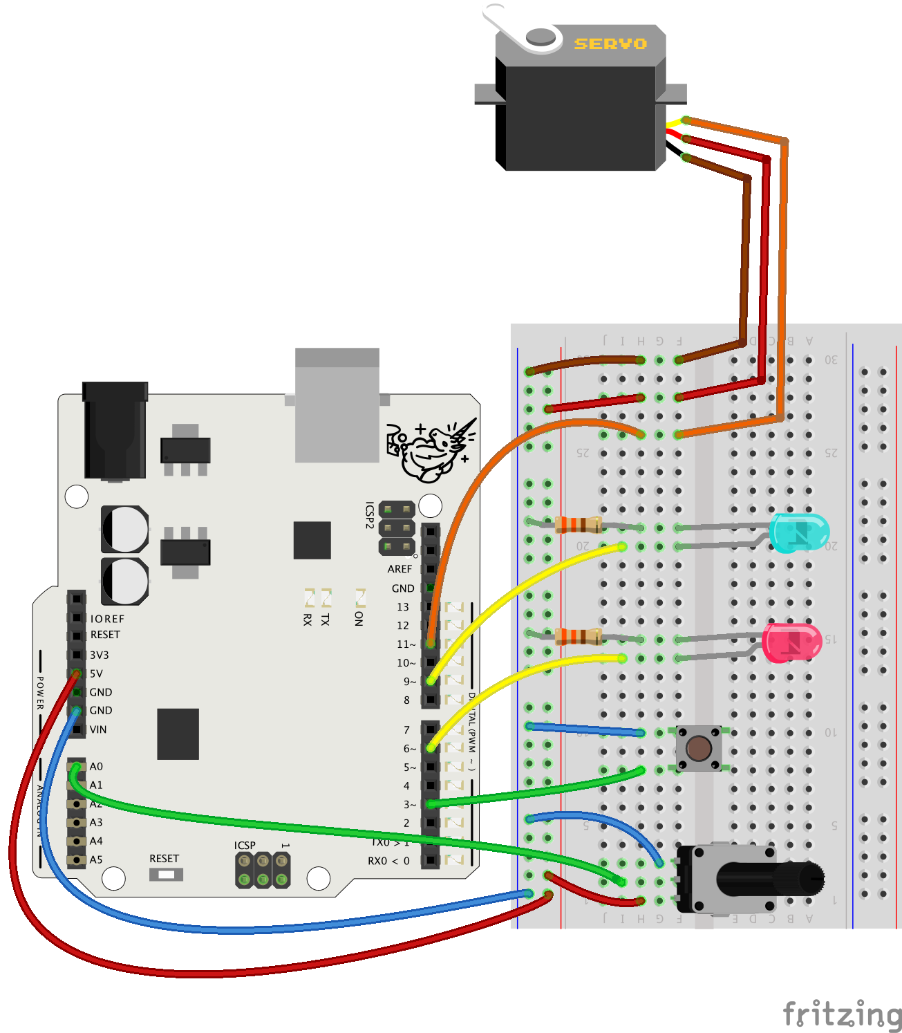
  • …to connect a servo motor
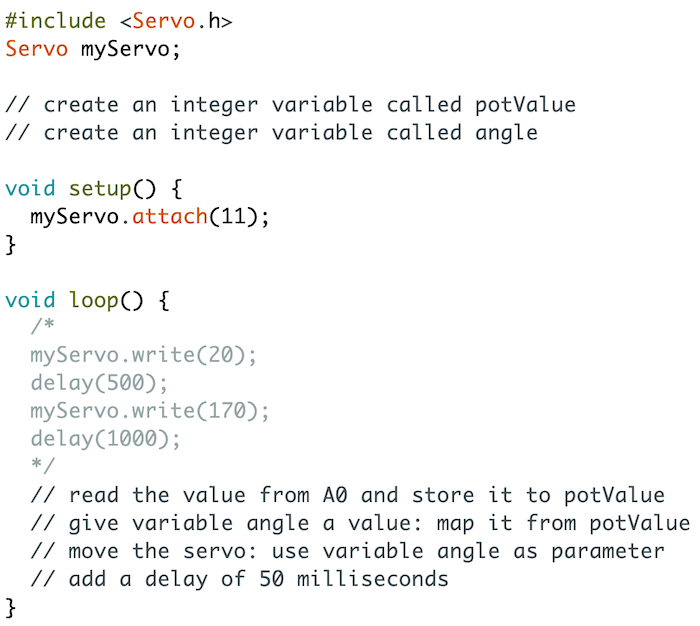
  • …to use the servo library to program servo motors
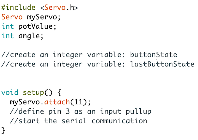
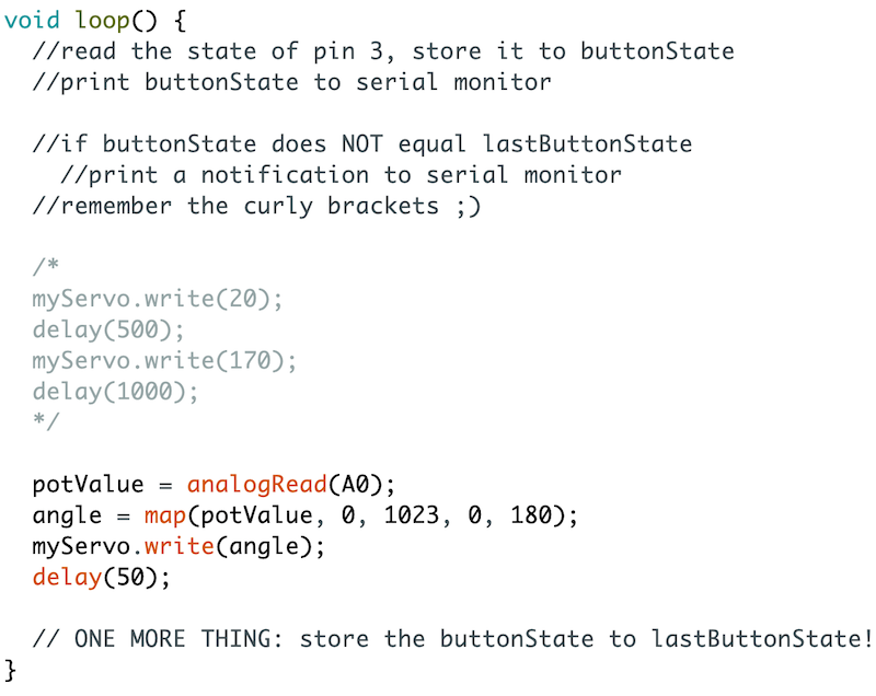
  • …to program the toggle functionality by following instructions: tracking button presses, activating things when a button is pressed and released after that
  • …new ways to make use of digital logic: using the NOT sign ( ! ) in conditions and to flip values to their opposites

Depending on the final exercise, the students also practice…

  • … creating a mechanism for the servo by making a small creeper robot or a moving mechanic prototype (Exercise 1: Mad Mechanisms)
  • … to code a servo to turn towards light using inputs from two LDR sensors (Exercise 2: Light Follower)

Slides and Lesson PLans

Feel free to use these slides to introduce the third chapter to the students!

There are some speaker notes attached to the slides. To see the speaker notes, click Options > Open Speaker Notes in the bottom panel.


Lesson plan suggestion

TimeWhat?
5-10 minMake sure everyone has the electronics components they need. SCRUM routine: Students explain to others: 1) what was the last thing they did on the previous lesson and 2) if they had any challenges they need help with. If students are shy to speak when others are listening, you can go and talk with them individually later.
5-10 minIntroduce the fourth chapter with the slides above.
40-50 min

Students work on Movement in Modes.
Go around in the classroom while the students are working and discuss briefly with each student. Talk especially with those who have had problems or seem to lack motivation. The most challenging new topic in this chapter is programming the button to control movement modes - see Educator notes for teaching tips and example code.

10-15 min

Ask the students if they have had any challenges so far.
If needed, copy the code from Educator Notes to Arduino IDE, show it on a big screen and discuss the difficult parts (eg. controlling movement modes with a button, controlling LEDs with the servoMode variable)

20-30 minStudents choose and work on an exercise:
1) Mad Mechanisms
2) Light Follower
10 -15 min

Demo session: everyone presents what they have made as their last exercise!

How does working with Arduino feel like? What were the most rewarding and most difficult things? What would you like to make next?

Total: 90-130 min


There are a lot of code examples in the educator notes throughout this page - we hope it’s useful! You’ll be able to assist the students in every phase of this task using these code examples.

What if the time is running out?

Skip Programming 5 - Signal Lights if you have a tight schedule!

Introduction

Transcript

Hi there! I'm Mikko from Mehackit and I'm going to show you how to make things move with Arduino. Electric motors are everywhere: in printers, surveillance cameras, toothbrushes, toys, cars and of course robots. The fun part about motors is: if it's controlled with electricity you can control it with an Arduino. We're going to start with a motor that's really easy to connect and program: the servo motor. Servos are used in robotics, radio-controlled toys, solar panels, factories and practically everywhere where you need really precise movement. Some servo motors move round and round but you'll be using a motor that moves 180 degrees, back and forth. You'll move the motor in different ways and control it with a potentiometer. You'll use the servo library, a ready-made collection of coding tools that makes using servo motors easier. You'll also learn to program different modes to your Arduino project. You can design different functionalities, like movement patterns, and activate them by pushing a button. To do this you'll learn even more about variables and how you can use them to check things. There's two exercises again to choose from. You can concentrate on designing your very own mechanisms and for this task you can use a variety of materials and things you have at hand. Maybe you'll be able to create a small robot that moves around. The other option is a mini project where you make a device that seeks light. It could be used for positioning solar panels for example. See you later!

Which of these statements about servo motors are true? There may be more than one correct option!

Parts


Do this

Collect these parts. In addition to them you will need an Arduino UNO or Mehackit Board, a USB cable, a breadboard and a bunch of jumper wires.

PartImageDescription
Servo motor (180 degree)Servo motor takes a position between 0 and 180 degrees, depending on how it's programmed. A servo has three wires, which are connected to a digital pin, to voltage, and to ground. The other kind of servo motor is called continuous or 360-degree servo.
Pushbutton

The button in the Mehackit Maker Kit is white, not brown.

Potentiometer

A potentiometer is a variable resistor that is adjusted by turning the knob. 

2 x LED, different colorsLEDs conduct electricity to one direction only. The longer leg is connected towards a numbered pin (0-13).
2 x resistor 330Ω (or 220Ω)

Resistors resist the flow of an electric current. The value of the resistor is measured in ohms (Ω). The resistance value is coded into the colored stripes (330Ω: orange, orange, brown and gold). You can replace the 330Ω resistor with a 220Ω one.


Circuit


Do this

Make a circuit according to the diagram below.

  • Connect the LEDs to pins 6 and 9 and ground (through two 330 ohm resistors)
  • Connect the button to pin 3 and ground.
  • Connect the potentiometer to A0 from the center.  Connect the sides to ground and 5V 
  • Connect the servo: ground wire (brown/black) to ground row, voltage wire (red) to 5V row, signal wire (orange/yellow/white) to pin 11. 

Why do you need to connect a signal wire from a digital pin to a servo motor?
Where do the LEDs get the voltage they need, in this circuit?

Programming 1: Sweep the Servo

Transcript

Let's get the motor moving! You'll start off with something new: you'll tell the program to use the servo library on the very first row. Libraries are great. They extend what you can do in a programming environment. They consist of pre-made code, sometimes really long pieces of it, and instead of writing all that code yourself, you can use the code in the libraries with short, custom commands. You'll learn more about libraries later on. This time using the servo library will unlock nice new commands for controlling servo motors. The first command from that library looks like this. To be exact, you create a servo object here. We won't go deep into programming with objects just yet so I'll keep it brief now. myServo is a bit similar to variables: its type, so to speak, is Servo and it has a name given by me: myServo. You always need to create a a servo object if you want to use all the fine commands from the servo library. You always use the name of that object together with those commands. Next, go to the setup part and tell the Arduino there's a servo connected to the pin 11. You don't use pin mode command, however, because servos have their own commands in the library. No-one can remember all libraries and their commands by heart so I'll check the reference. Here's all the commands you can use with servo objects. Attach() sounds promising. Attach the Servo variable to a pin... this is what you need. Here's an example, too. First the name, then a period, and attach. The only parameter you need is the pin number, 11. You'll move the servo in the loop part. Again, you'll type the name first, then period. You make the servo move with the write command. The number in the parentheses is the angle. The smallest possible value is 0 and the biggest is 180 because this type of a motor moves 180 degrees. Let's make the motor move between two different angles. It's not very difficult for you anymore. Type in a delay, and then a second write command with a new angle. And another delay. Let's upload the code. Great success! It's moving back and forth! This could be the basic movement for a little creeper robot or something. Try it out now and test different angles, too.

Do this

Follow the instructions in the video and program the servo motor to sweep back and forth!

  • You can copy and paste the code below to your Arduino IDE and write the missing parts:
// include the servo library
// create a servo object and name it myServo

void setup() {
  // tell the Arduino that myServo is attached to pin 11
}

void loop() {
  // move the servo to an angle (0-180) with write command
  // code a small delay
  // move the servo to a new angle with write command
  // code a small delay
}
  • Upload your code and see what happens!

EXTRA

  • test it with different angles and different delay values!
  • What happens if the delay value is very small…?

Which of these statements is false?

Educator notes

Key points:

  • including the servo library in the code, creating a servo object
  • setting the servo pin up with myServo.attach
  • moving the servo back and forth with myServo.write

Example code

//include the servo library:
#include <Servo.h>
//create a servo object and name it myServo:
Servo myServo;

void setup() {
  //tell the Arduino that myServo is attached to pin 11
  myServo.attach(11);
}

void loop() {
  //move the servo to an angle (0-180) with write command:
  myServo.write(20);
  //add a delay:
  delay(500);
  //move the servo to a new angle:
  myServo.write(170);
  //add a delay:
  delay(1000); 
}

What if the servo doesn’t move?

  • With very small delay values the motor may not move at all. In this case, the program may be executed so fast the servo motor doesn’t have time to move from one position to another!
  • If the student’s code is written as above, suggest they check the connections on the breadboard.
  • On rare occasions the servo motor may be broken. The plastic gears may break if you turn the servo manually.

Programming 2: Manual Control

Transcript

You got the servo moving back and forth on its own. A good start. Now, let's control the motor with the potentiometer. Here's the previous code. Now I don't want the motor to sweep like that but I might want to use this code later on. Here's a nice trick for saving useful parts of code for later use. That's the previous movement pattern right there. I'll comment it out which makes the code invisible to the Arduino. A slash and an asterisk to the start. To the end: first an asterisk and then a slash. Those symbols tell the Arduino to skip all code between them. You could write two slashes in front of every line, too, but that means more typing. Back to the start, then. What kind of variables do you need? You'll need one for the potentiometer values. And make another one to store the servo angle. Remember you can give initial values to variables, too, when you create them. But that's optional and this time it won't make a difference. The next part is pretty familiar. First read the value from the analog pin 0 and store it to the potValue variable. potValue must be mapped to a useful range for the servo. So, the variable angle receives a value which is the result from the map command. The map command takes the potValue which has the range from 0 to 1023 and then the command maps that value to a new range which is from 0 to 180. That's the range of angles the servo can get. And finally a small delay to stabilize the servo behavior a bit. Time to upload and see what happens. Ok, let's turn the potentiometer. You could control a robot arm like this, or turn the wheels of a remote-controlled car, or something. Your turn. Try out this code now!

Do this

Follow the instructions in the example below and make the servo react to the potentiometer.

  • use  /*  and */  to turn the four commands you wrote earlier into comments

Code example:

Check the video again if you don't remember how to write the missing commands.


Which of these commands maps the potentiometer values to servo angles correctly?
Why did you have to turn a piece of your earlier code into a comment?

Educator notes

Key points:

  • “commenting out” a chunk of code to save it for later use
  • mapping the value from the potentiometer to a servo angle

Example code

#include <Servo.h>
Servo myServo;

//create integer variable potValue:
int potValue;
//create integer variable angle:
int angle;

void setup() {
  myServo.attach(11);
}

void loop() {
  /* 
  myServo.write(20); 
  delay(500); 
  myServo.write(170); 
  delay(1000); 
  */

  //read the value from A0 and store to potValue:
  potValue = analogRead(A0);
  //give variable angle a value: map it from potValue:
  angle = map(potValue, 0, 1023, 0, 180);
  //move the servo with angle as parameter:
  myServo.write(angle);
  //delay of 50ms:
  delay(50);

}

Programming 3: Track Button States

Transcript

Now you can move the servo motor in two different ways: there's the back-and-forth mode and the mode where you control the servo with the potentiometer. Next you'll learn to switch between those two modes by pressing a button. First you will control the servo with the potentiometer. If you press the button once the servo starts to sweep back and forth. If you press again it goes back to manual control. In the end you'll program signal lights, too, so you know which mode is on. To do this you will need to track the state of the button and the movement mode of the servo. And to track any events you need variables. Let's start with the button. First you need a variable to store the state of the button. The button has two possible states: it is pressed or it isn't pressed. Go to the setup part and set the button pin 3 as INPUT_PULLUP. Start the serial communication, too, so you can check what's going on with your variables. In the loop part you'll check the button with digitalRead and store the information to the buttonState variable. Print it to the serial monitor, too. Now let's see what this prints to the serial monitor. When I press the button I get the value 0 and when the button's up it's 1. But hey, wasn't digitalRead supposed to equal HIGH when the button's up and LOW when it's pressed? Well they're both okay. You can always replace the text HIGH with 1 and LOW with 0 when you're programming Arduino. Every time you press and release the button the servo should switch from one movement mode to another. So it's not enough to know if the button is right now up or down. You need to know when it changes from up to down and up again. You have to check after every loop run if the state of the button has changed or not. To do this you have to store the button state from the last round somehow. First, make a new variable just for that. You must store the button state in the end of every loop run. And in the beginning of every loop you need to compare if the previous state is different from what the state is now. There's a new operator inside the if statement. These symbols together mean "not equals" in programming. In plain English: if the state of the button right now is not the state it had last round, then something happens. And what happens? Write this code and try it out now.

Do this

Create two new variables

Fix the setup part 

Next, fix the loop part.

  • check the video again if you're having trouble!
  • There's also a hint in the multiple choice questions below!

Upload the program, open the serial monitor and press the button. Do you see a notification in the serial monitor? When does this happen?

  1. if (buttonState != lastButtonState) {
    Serial.println("It changed!");
    }
    
  2. if (buttonState == lastButtonState) {
    Serial.println("It changed!");
    }
    
  3. if (buttonState == 1) {
    Serial.println("It changed!");
    }
    
Your program should print a notification when the button state changes. Which one of the if statements above will do the trick?

What is the value of lastButtonState in the end of a loop run when the button is held down?

Educator notes

Key point:

  • learning to compare the state of the button between two loop runs

Example Code

#include <Servo.h>
Servo myServo;
int potValue;
int angle;
//create an integer variable to store the button state now:
int buttonState;
//create an integer variable to store the button state in the last loop run:
int lastButtonState;

void setup() {
  myServo.attach(11);
  //define pin 3 as input pullup:
  pinMode(3, INPUT_PULLUP);
  //start serial communication:
  Serial.begin(9600);
}

void loop() {
  //store the current state of the button:
  buttonState = digitalRead(3);
  //print the current state of the button:
  Serial.println(buttonState);
  //check if the current button state is the same as last round:
  if(buttonState != lastButtonState) {
    //if the state isn't the same, print this:
    Serial.println("Hey it changed!");
  }
  /*
  myServo.write(20);
  delay(500);
  myServo.write(170);
  delay(1000); 
  */
  potValue = analogRead(A0);
  angle = map(potValue, 0, 1023, 0, 180);
  myServo.write(angle);
  delay(50);
  
  // store the button state to lastButtonState:
  lastButtonState = buttonState;

}


Programming 4: Change the Mode

Transcript

Learning to track button states may feel a bit tricky. At least I found it tricky when I started to learn Arduino programming. It's different from just tracking if the button is pressed. If you change the motor mode every time Arduino notices the button is pressed, it'll change back and forth super fast, because the loop is so fast. You get so many readings in a short time. You need the track when there's a change between two loop runs and only do something when that change happens. That's the thing. So when should the servo mode change? When the button has been pressed and released after that. This part is tracking the button state. Now you will add a new condition inside it. What it says now is: check if there was a change and if there was, also make sure the button state is now 1, which means the button's been released. If it is, then print this text. Let's see if this works. Alright! Now let's make the servo really change that mode. Make a new variable called servo mode. Let's say 0 means the servo will go back and forth and 1 means manual control. To make this really clear let's give t he servo a starting mode 1. So here's the part that checks when the servo mode must change. Let's do a great coding maneuver there. Now this is a really useful trick. If you have a variable that can only have two values which are opposite to each other, you can flip a value to its opposite. 0 and 1 are opposites in Arduino programming. Flipping is done with an exclamation mark. I'll print the value so you can see how it works. So here are the two movement modes of the servo. Back and forth, and here: manual control. You have to wrap those modes into if statements. Remove the comment symbols first. Type if servoMode equals 0 and add curly brackets here and here. The other mode goes inside a second block. Here you'll write a new thing: else. If servoMode is 0, the first block is executed. Else, only if it's not 0, the second part is executed. You could also write else if (servoMode==1). Now that's a really clear way to write it. But "else" is enough, too, when you only have two possible modes. So, when the servoMode is 0, computer keeps repeating these commands and when servoMode is 1, it repeats these commands. I'm sure you'll notice a little problem with this device now. It feels a bit slow to change the mode at times. We'll look into that soon. But now it's your turn to write some code.

Do this

Continue your code adding one more variable to the beginning:

  • Next, fix the loop part - check the video again if you have trouble with it!
    Add Serial.print and Serial.println commands to see what's going on with your variables.

If everything went well, the servo now changes from sweeping mode to manual control with a press of the button! 

Note: It takes a while when the mode changes from sweep to manual.


  1. if(buttonState != lastButtonState) {
          servoMode = !servoMode; 
    } 
    
  2. if(buttonState != lastButtonState) {
        if(buttonState == 1) {
          servoMode = lastButtonState; 
        }
    } 
    
  3. if(buttonState != lastButtonState) {
        if(buttonState == 1) {
          servoMode = !servoMode; 
        }
    }
    
Which of these options will change the servo mode in your program correctly?

Educator notes

Key points:

  • using a variable (servoMode) to define different servo modes
  • defining with if statements what happens when servoMode gets values 0 or 1
  • changing the servoMode value when the button is pressed and released
  • It’s a good idea to add some Serial.print / Serial.println commands to the code, especially if something is wrong and it’s hard to tell what it is! Print for example the servoMode variable if the mode doesn’t change, or the potValue if the manual mode doesn’t work well.

Example code

#include <Servo.h>
Servo myServo;
int potValue;
int angle;
int buttonState;
int lastButtonState;
//integer variable for storing the servo mode, initial value 1:
int servoMode = 1; //manual: 1, sweep: 0

void setup() {
  myServo.attach(11);
  pinMode(3, INPUT_PULLUP);
  Serial.begin(9600);
}

void loop() {
  buttonState = digitalRead(3);
  Serial.println(buttonState);
  
  if(buttonState != lastButtonState) {
    if(buttonState == 1) {    //if the button is up
      servoMode = !servoMode; //flip the value to its opposite
    }
  } 
  
  if (servoMode == 0) { //if servoMode is 0, go to sweep mode
    myServo.write(20);
    delay(500);
    myServo.write(170);
    delay(1000); 
  } else {             //else go to manual mode (servoMode is 1)  
    potValue = analogRead(A0);
    angle = map(potValue, 0, 1023, 0, 180);
    myServo.write(angle);
    delay(50);
  }
  
  lastButtonState = buttonState;
}

Programming 5: Signal Lights

Transcript

This is a decent little device now. The servo mode changes when you press the button. But there's an annoying feature. When the motor's sweeping back and forth, you sometimes need to press the button for a long time before the mode changes. Like this. That's because of the delay commands in the sweep mode. Delay is an easy command to use but it stops everything in an Arduino program for the time defined in the parentheses. Arduino can't check the button state with digitalRead until these two delay commands have passed. That's a bit tricky. There is a workaround. You could use one of Arduino's internal clocks to time events better, but that's another topic and you'll learn more about that a bit later. We'll make a quick fix. Let's use these LED lights to signal when a button press is registered. It will make using this device a lot easier. The first thing to do is of course setting the LED pins as outputs. A great place to turn a signal light on is here, right when Arduino has detected the button has been pressed down but it's not released yet. So the light will tell the user they can stop pressing the button already: the mode is about to change soon. But - should it be HIGH or LOW or what? I'll show you a cool thing, just watch. Let's upload this. Okay, now, when the button is pressed, one light is turned on, one is off. When I release, the servo mode changes. Again: button is pressed, lights change, release, the mode changes. The lights tell me when Arduino has noticed the button is pressed down and I know I can let go of it already. I used the servoMode variable to control the LEDs. The value of servoMode is always either 1 or 0. As I said earlier, in Arduino programming you can always use 1 instead of HIGH and 0 instead of LOW. And it works with LEDs, too. So, when servoMode is 0, the first LED is off. When it's 1, the first LED is on. With the NOT sign, the exclamation mark, you can make sure the other LED is always in the opposite mode. Pretty handy, isn't it?

Do this

Make the signal lights work!

  • First, fix the setup part:
  • You only need to change the beginning of the loop part:

At which phase do the signal lights change?

Educator notes

Key point:

  • signaling with LED lights when the servo mode is about to change (when the button is pressed down)
  • If you’re running out of time, this phase can be skipped.

The Final Code

#include <Servo.h>
Servo myServo;
int potValue;
int angle;
int buttonState;
int lastButtonState;
int servoMode = 1; //manual: 1, sweep: 0

void setup() {
  myServo.attach(11);
  pinMode(3, INPUT_PULLUP);
  //define pins 6 and 9 as outputs:
  pinMode(6, OUTPUT);
  pinMode(9, OUTPUT);
  Serial.begin(9600);
}

void loop() {
  buttonState = digitalRead(3);
  Serial.println(buttonState);
  
  if(buttonState != lastButtonState) {
    //use digitalWrite to turn one LED on and the other off.
    //instead of HIGH or LOW, use servoMode and !servoMode as parameters
    digitalWrite(6, servoMode);
    digitalWrite(9, !servoMode);
    if(buttonState == 1) {    //if the button is up
      servoMode = !servoMode; //flip the value to its opposite
    }
  } 
  
  if (servoMode == 0) { //if servoMode is 0, go to sweep mode
    myServo.write(20);
    delay(500);
    myServo.write(170);
    delay(1000); 
  } else {             //else go to manual mode (servoMode is 1)  
    potValue = analogRead(A0);
    angle = map(potValue, 0, 1023, 0, 180);
    myServo.write(angle);
    delay(50);
  }
  
  lastButtonState = buttonState;
}

Learn More: Motors and Power

Transcript

Servo motors are nice but there are other motors you can use with Arduino, too. You used the servo that moves back and forth but there are also servos that are continuous. They move 360 degrees. Servo motor consists of gears, a microchip and another kind of a motor called DC motor. Servo is easy to control by programming, thanks to all these extra parts, but with the right components you can control a DC motor, too. Fun fact: DC stands for direct current which is the type of current you get from a battery or a USB cable. If you add an uneven weight to the shaft you can make a vibration motor. There are DC motors with gears, too. They move a bit slower which is sometimes useful. You can even use DC motors to pump water. Another motor worth mentioning is the stepper motor. Stepper motors are great when you need more control over the rotation. Steppers can move, well, one step at the time so you can position them accurately. Sometimes motors require more current than an Arduino can give. In this case you will need an external power supply to keep the motor going. Just one servo in your Arduino circuit might already cause trouble with current and that's when the servo does something weird. The solution could be using an external power supply for the servo, for example a battery pack like. Servo is the only kind of motor you can connect directly to an Arduino. With the other types you need parts like transistors or motor driver chips to manage the extra current they need. But no need to worry, you'll learn more about managing all those motors in your future projects.

You can't connect most motors directly to Arduino pins. Why?

Educator notes

Learn More: Motors & Power

You might have problems with servo motors due to insufficient voltage or current. The current may be too weak especially if:

  • You're using multiple servos at the same time.
  • You're using for example a 9 V battery to power up the Arduino.

You'll notice the lack of power when the servo doesn't rotate smoothly.. Here are a couple of hints on how you can guarantee your servo receives enough current:

Use a separate power supply for the servos

An option is to use a separate power supply for the servos. The servos usually work with a voltage of 4-6 V (Arduino provides 5 V). For example, 4 AA batteries provide a voltage of 6 V, which is enough for multiple servos (4 x 1.5 V = 6 V).

In the picture, Arduino uses a voltage of 9 volts, while the servos use a voltage of 6 volts! Arduino's processor runs on a different power supply than the servos, which diminishes the load on the 9 V battery. The positive terminal of the 4-battery-pack has been connected to the servos' voltage wire and the ground terminal to servos' ground wire and to Arduino's ground. You can still use a USB cable to connect Arduino to the computer, which will then take care of powering up the board.

Use a mobile phone powerbank

A powerbank can easily be connected to Arduino, because it has a USB connection. The lifetime of the battery is at least 2500 mAh, when the lifetime of a 9 V battery is usually only about 500 mAh. At best, a powerbank can provide power to both an Arduino and the servos connected to it.

Use a power supply which connects to a power socket

Learn more about external power supplies for example on the Arduino website