Exercise 2: Burglar Alarm

Transcript

Aha, gotcha! Now you get to fight evil forces with Arduino. Time to put a stop to all those nasty thiefs with a burglar alarm. 
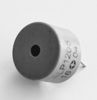
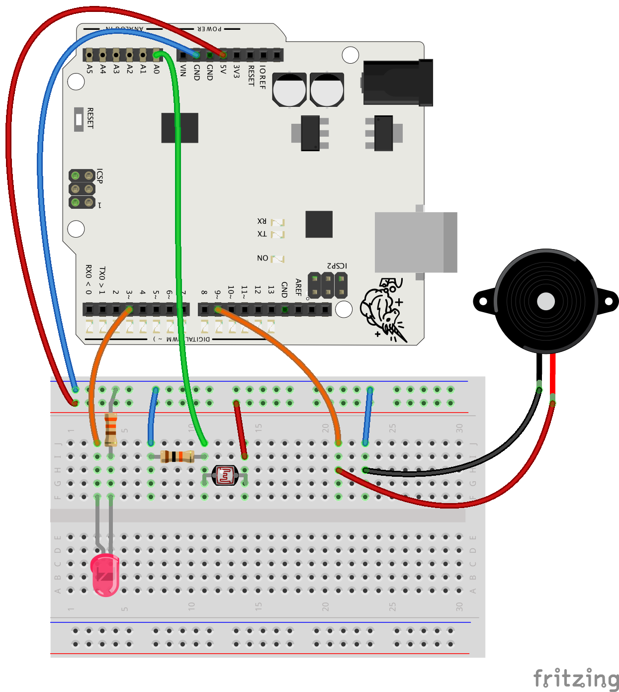
The device is made with familiar components. There is an LDR, a piezo and an LED. I'll show you the basic setup and if you have the time, you can add more features and also figure out how to hide the alarm. Let's check out the code quickly. You will write most of the code yourself in this exercise. First you need to create a variable to store the sensor values. Remember the semicolons. Then you move on to the setup part. Looks like you need to use the Serial.begin command. Here you have to set the pin mode for the piezo and the LED pins. The loop part looks like this. First you check the sensor data with the analogRead command, and store the value to the variable. And here you'll print the value to the serial monitor so you can check what it is. The if statement comes next. 
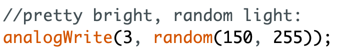
Put everything you want to happen when the alarm goes off between the curly brackets. Play a note with the tone command and turn the light on. Use the analogWrite command with the LED. Just give it a good value between 0 and 255. After the delay comes the second part of this alarm. Here is a new note and the light goes dim. One more delay to the end. These are just suggestions of course Make the sounds and light effects you like the best. At this point you should test how the alarm works - and maybe it doesn't. Fixing it is easy. Open the serial monitor, look at the sensor values and change the condition of the if statement so it works like it should. You also need to make sure the LED is always off then the valuable treasure is on the LDR sensor. That you do on the last line here, outside the if statement.

Do this

Code a burglar alarm which makes noise and flashes lights when an object is stolen.

  • Find the parts and make the circuit - instructions below
  • Program the device - use the code example and the instructions in the video!

Code example (copy and paste to Arduino IDE if you want) :

// create and integer variable ldrVal


void setup() {
  // Start serial communication at speed 9600
  // set piezo pin 9 to output
  // set LED pin 3 to output
}

void loop() {
  // store the value from pin A0 to ldrVal
  // print ldrVal to serial monitor
  // small delay of 20 milliseconds

  // if ldr gets light
    //play a note with tone command
    //turn LED on with analogWrite
    //delay of 100-1000ms
    //play some other note
    //change LED brightness with analogWrite
    //delay
  //remember the curly brackets ;)
  
  //turn LED off with analogWrite
}

If you have trouble with the exercise:

  • watch the video again
  • check out the earlier instructions of this chapter
  • discuss the exercise with others and the teacher
  • use Arduino Reference

Tips

  • Fix the condition of the if statement if needed: check the serial monitor and find a good threshold value  
  • Think about how to hide the alarm device. Could you hide all the components in a box? Can you use extension wires with the LDR so the rest of the alarm device can be hidden? How to position the valuable object?

EXTRA

  • Give the LED an extra twist with random brightness values! Here's how:
  • random(min, max) creates a random number between given minimum and maximum values. It's a useful command!
    Note: Be careful with parentheses - it's not a typo, you really need two closing parentheses  ))  in the end of the command.

  • Add a second LED to the prototype.

  •  Want to stick to regular beeping or imitate police sirens? Or compose a melody? Use many notes with delays in between to write a melody.

  • Improve the light and sound effects. Add a plastic cup around the piezo speaker to amplify the sound. Enhance the light effect of the LED (check out Exercise 1 in the first chapter for ideas)!

When you learn more about how to work with Arduino, you can explore making a wireless alarm system which can send you an alarm message wherever you are using wi-fi!


Parts and Circuit

In addition to these parts you will need an Arduino UNO or Mehackit Board, a USB cable, a breadboard and a bunch of jumper wires.

PartImageDescription
LDR (light-dependent resistor, photoresistor)The resistance of an LDR changes with the amount of light. The brighter it gets, the less an LDR resists an electric current.
LED

Choose an LED you like - maybe something bright and alarming?

Resistor 10kΩ (10,000Ω )

A 10 kilo-ohm (10,000 ohm) resistor is used with an LDR. Stripe colors: brown, black, orange, gold

Resistor 330Ω (or 220Ω)

330Ω and 220Ω resistors are used with LEDs. Stripe colors for a 330Ω resistor: orange, orange, brown, gold

Piezo speaker  

A piezo can transform a quickly alternating voltage into sound. Some piezos can be used as a knock sensor. 


Circuit

After you've made this circuit, check out the programming instructions above


Educator notes

This exercise is meant to be done with few instructions: the full code is not shown in the video. The code example consists of comments: the students should write their own code below the comments or replace them.

If the exercise seems too difficult, feel free to give the students more detailed instructions.

  • show the Arduino IDE from your own computer on a screen and write the example code (see below) together with the students line by line. Or, you can show them how to write the most difficult parts only. Discuss the code: what does each command do? What are the parameters?
  • Don’t worry if you don’t yet remember every command by heart! Be a coach instead of an expert and let the students take an active role in learning themselves. Students should discuss what they’ve learned with each other and review information in the previous chapters and in the Arduino Reference.

Example Code

// create an integer variable ldrVal
int ldrVal;

void setup() {
  // Start serial communication at speed 9600
  Serial.begin(9600);
  // set piezo pin 9 to output
  pinMode(9, OUTPUT);
  // set LED pin 3 to output
  pinMode(3, OUTPUT);
}

void loop() {
  //read the sensor pin A0 and store the value to ldrVal
  ldrVal = analogRead(A0);
  // print ldrVal to serial monitor
  Serial.println(ldrVal);
  // small delay of 20 milliseconds
   delay(20);

  //if ldr gets light
  if (ldrVal > 600) {
    //play a note with tone command
    tone(9, 1200, 800);
    //turn LED on with analogWrite
    analogWrite(3, 255);
    //wait
    delay(200);
    //play another note
     tone(9, 900, 800);
    //change LED brightness
    analogWrite(3, 100);
    // an alternative for the previous command (test different values):
    // analogWrite(3, random(50,100));
    delay(200); 
  }
  //when ldrVal is below 600, LED should be off:
  analogWrite(3, 0);