Transcript
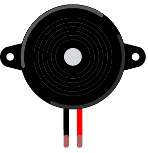
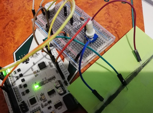
Next you'll make a musical instrument
you can play with light and shadows. Sounds mysterious,
doesn't it? Electronic instruments that make use of sensors are not a new thing.
Theremin, one of the first instruments like this, was patented already in 1928. In your instrument the amount of light
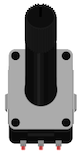
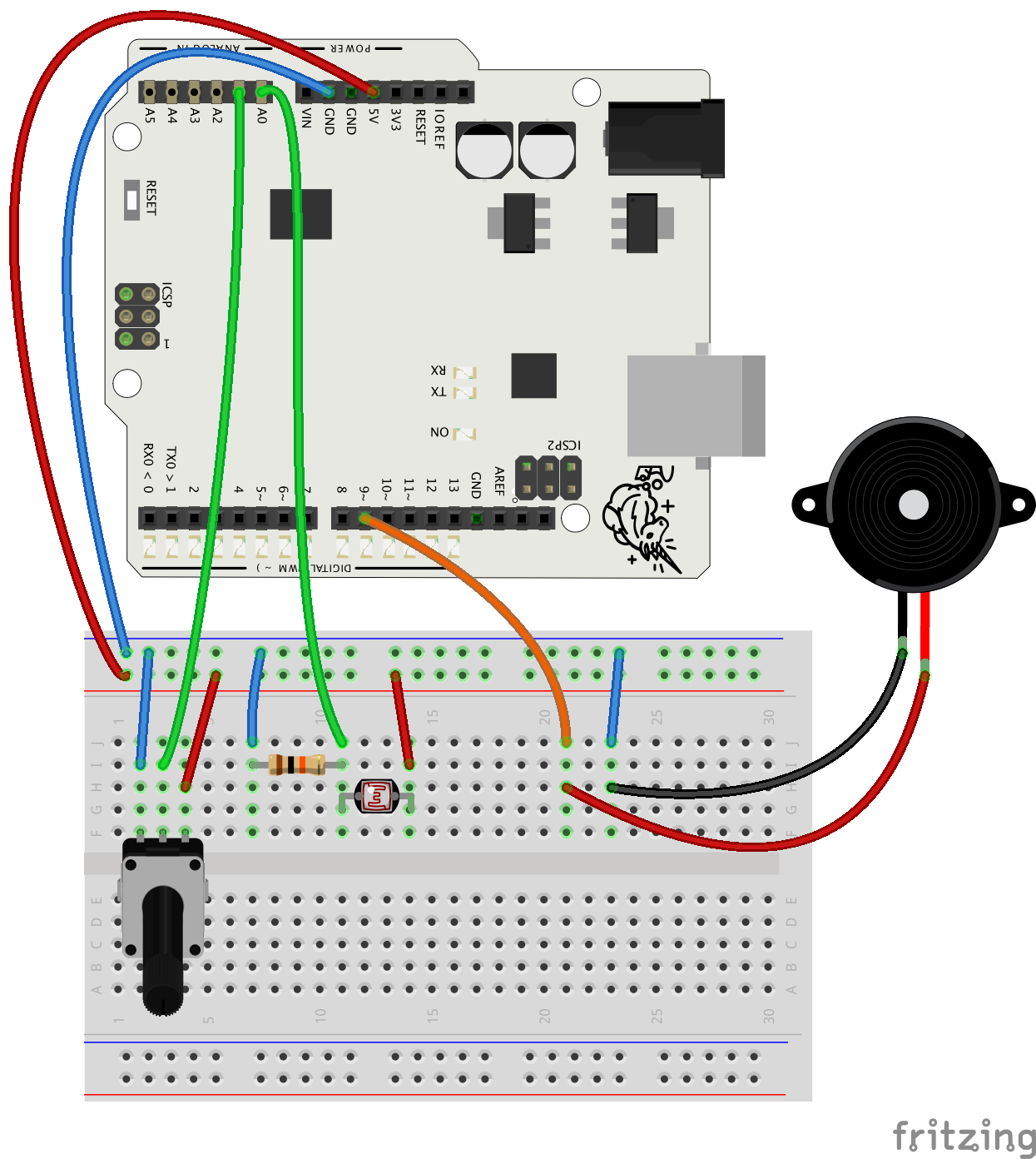
will adjust the pitch. You'll control the rhythm with a new part called
potentiometer, which is a familiar component from many electronic devices.
Potentiometer is also a sensor so you learn how to use two sensors in the
same project. And to manage all the data from different sensors, you'll need
variables again. I love this project so let's get going!