Automatic Dimmer

Educator notes

Educator Intro

Transcript

Hi! I'm Viktoriya from Mehackit. This chapter is all about sensors. How to detect what's happening around you and how to use that data to make sensing, interactive devices. We'll cover the very basics of analog signals and how digital devices like Arduino deal with the analog world. You'll make an automatic dimmer for an LED. Apart from sensors, you'll also learn how to control the brightness of an LED. You'll also create an Arduino-based musical instrument you play with light and shadow. You'll continue working with variables - you need them to store the values from your sensors. You'll go through the first tasks step by step, and the final exercises require the students a bit more independent attitude. Once again, the students can choose from two options. The first exercise encourages the students to observe light phenomena around them and to use those observations to improve the musical instrument they've made. They can emphasize crafts, design or code in this mini project. The second exercise, the burglar alarm, is a more straightforward coding task. This is a good exercise for rehearsing all the programming concepts we've been through. In case you have students who have difficulties with basic programming, exercise 2 might be a good recap task for them. We'll keep it simple and use only two sensors for now: the light-dependent resistor and the potentiometer. These are good for learning the basics and you'll get to know more sensors later on. You'll practice the sensor workflow in this chapter. You'll monitor the sensor values, use those values in conditional statements or map the values to a new range to control different devices. You'll upload the code to Arduino and see if the device does what you want. And when you need to fine-tune your creation you start over again. See you soon!

Duration 1,5 - 3h

Learning Objectives

In this chapter the students will learn…

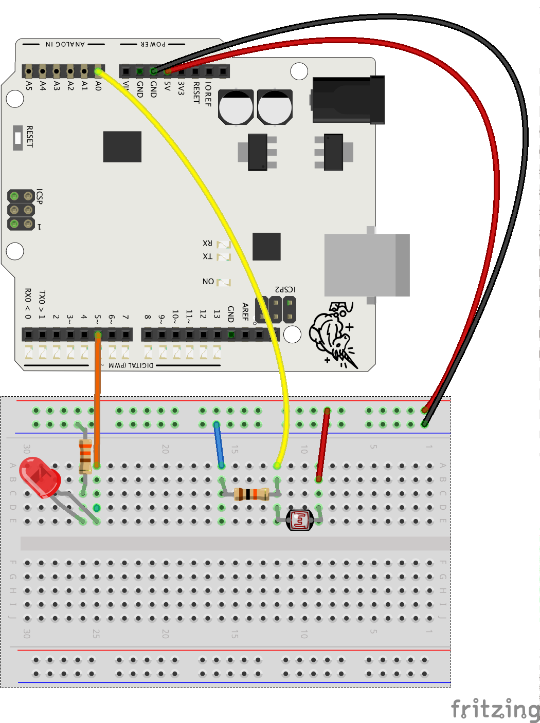
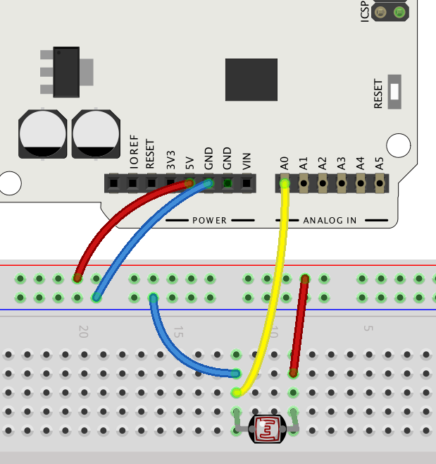
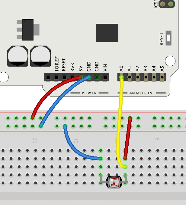
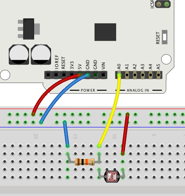
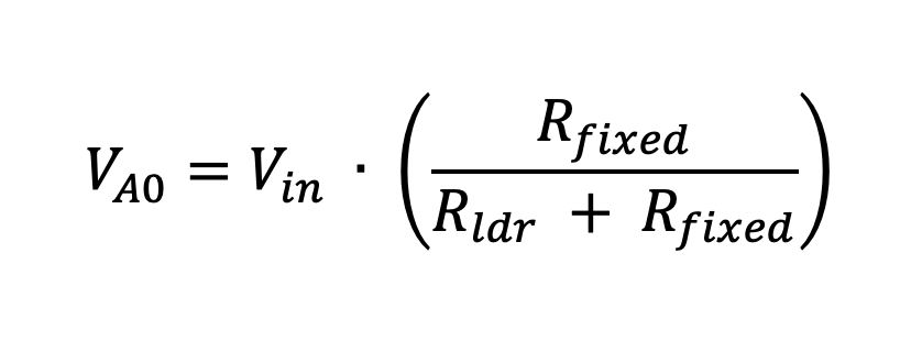
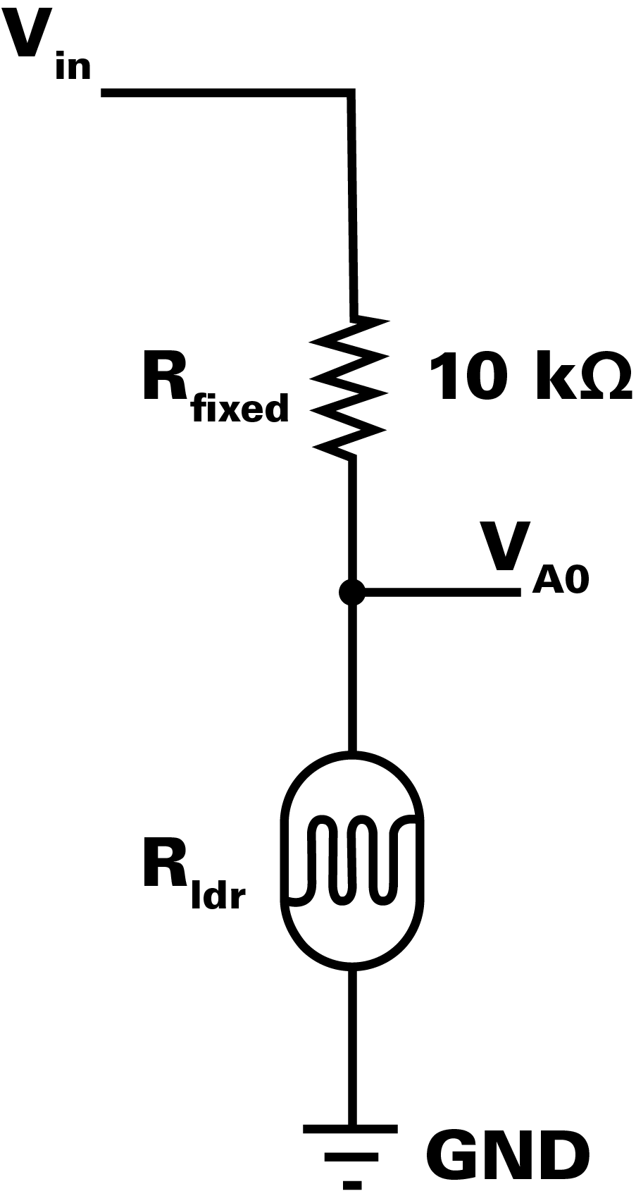
  • … the workflow with simple analog sensors (e.g. light-dependent resistors, potentiometers)
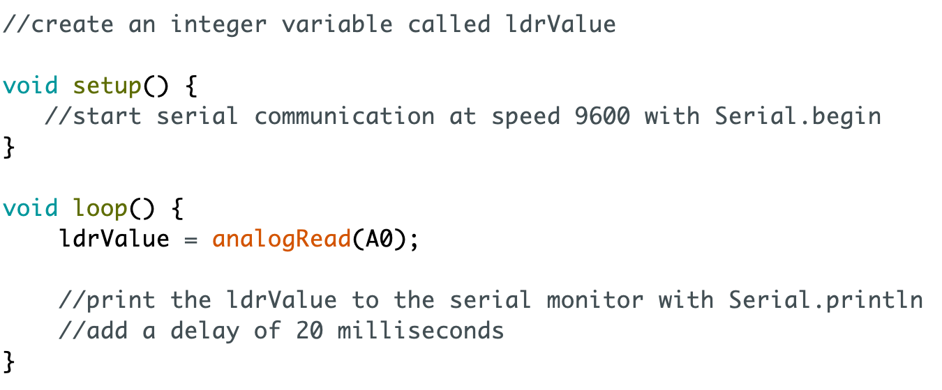
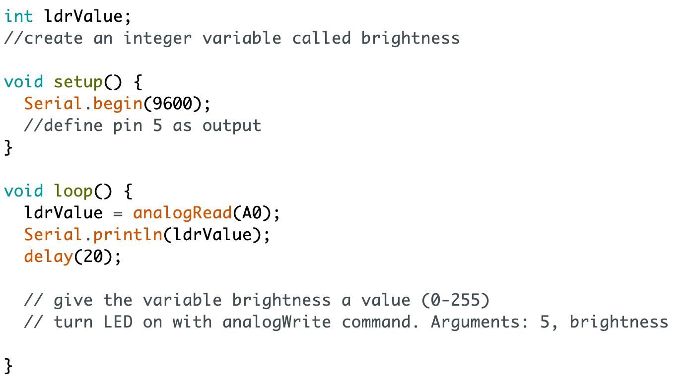
  • … to read sensor values from analog pins and to store them into variables
  • … to monitor sensor values using serial communication
  • … to control devices like LEDs and piezo speakers based on sensor data
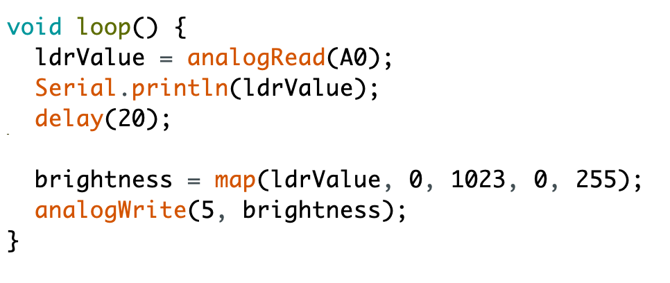
  • … to map sensor values to a new range
  • … to simulate analog signals to control LED brightness

Depending on the final exercise, the students also practice either…

  • … observing light and shadow phenomena and using crafts skills to continue developing an Arduino-based instrument (Exercise 1: Improve the Musical Instrument)

or

  • … building, coding and testing a burglar alarm prototype (Exercise 2: Burglar Alarm)

Slides and Lesson Plans

Feel free to use these slides to introduce the third chapter to the students!

There are some speaker notes attached to the slides. To see the speaker notes, click Options > Open Speaker Notes in the bottom panel.


Lesson plan suggestion

TimeWhat?
5-10 minMake sure everyone has the electronics components they need.
SCRUM routine: Students explain to others: 1) what was the last thing they did on the previous lesson and 2) if they had any challenges they need help with. If students are shy to speak when others are listening, you can go and talk with them individually later.
5-10 minIntroduce the third chapter with the slides above. 
20-30 min

Students work on Automatic Dimmer.
Go around in the classroom while the students are working and discuss briefly with each student. Talk especially with those who have had problems or seem to lack motivation. 

5-10 min

Discuss the challenges so far.
If needed, copy the code from Educator Notes to Arduino IDE, show it on a big screen and go through the parts that have been difficult.

20-30 min

Students work on Noises from the Dark.
Encourage the students to experiment: change the rhythm, make only high or low sounds...
See the Educator Notes for teaching tips and example code.

10 min

Reflection discussion: What has been most interesting? What feels difficult? 
Go through the code together if needed.

Introduction to the exercises: give a time limit of eg. 20 minutes!

20-30 minStudents choose and work on an exercise: 
1) Improve the Musical Instrument
2) Burglar Alarm
5-10 min

End the lesson (or start the next) by going through a couple of mini projects the students have made. 

Total: 90-140 min

Introduction


Parts

Do this

Collect these parts. In addition to them you will need an Arduino UNO or Mehackit Board, a USB cable, a breadboard and a bunch of jumper wires.

PartImageDescription
LDR (also called light-dependent resistor, photoresistor, photocell, light sensor)The resistance of an LDR changes with the amount of light. The brighter it gets, the less an LDR resists electric current.
LEDLEDs conduct electricity to one direction only. The longer leg is connected towards a numbered pin (0-13).
Resistor 330Ω (or 220Ω)

Resistor resists the flow of an electric current. The value of the resistor is measured in ohms (Ω). The resistance value is coded into the colored stripes (330Ω: orange, orange, brown and gold). You can replace the 330Ω resistor with a 220Ω one for this task.

Resistor 10kΩ (10,000Ω )

10 kilo-ohm (10,000 ohm) resistor is used with an LDR. Stripe colors: brown, black, orange, gold


Which direction does current flow in an LED?

Educator notes

As alternative for an LDR you can use a phototransistor, as well. There are different models of phototransistors which vary slightly, so you will need to do an online search to find out how your particular component should be connected to an Arduino (which resistor to use etc.). Phototransistors react faster than LDRs - a good feature in some projects!

Circuit


Do this

Make a circuit according to the diagram below.

  • Connect the LED to pin ~5 and ground (through a 330 ohm resistor)
  • Connect one leg of the LDR to 5V row
  • Connect the 10 kilo-ohm resistor to ground and to the same row with the other LDR leg
  • Connect the row with one LDR and one resistor leg to pin A0

What's special about Arduino's pins marked with the symbol ~?

Educator notes

This is the so-called voltage divider circuit. It's not covered in the student material, as there is already quite a lot of new material introduced in this chapter. Understanding the voltage divider is not considered obligatory in order to proceed with Arduino exercises. But the concept may be related to your curriculum - in case you want to explain the physics behind this technique with your students, here's an explanation to get you started!

Arduino's analog pins can measure voltage changes between 0-5V. Light-dependent resistor, LDR, is a component that has a variable *resistance, *which is something that the Arduino can't measure directly. So you need to be able to measure the change in the voltage of your circuit caused by the light-dependent resistor.

If you only connect one LDR to your circuit, wouldn't it be enough? Just read the sensor values with a wire between the LDR and ground wire, or LDR and voltage wire? Feel free to test it.

If you connect a wire to A0 from between the ground wire and LDR and then check the reading with analogRead, you only get the value 0:

If you connect to A0 between the voltage wire and LDR and check the reading with analogRead, you only get the value 1023.

Why won't these circuits work?

If you try to measure a voltage change with a wire directly connected to ground (which is the case in the first image), the voltage in that point is 0V. And if the wire is connected to the other end, directly to the 5V pin, the voltage measured at that point is 5V. 

To measure the actual voltage drop the LDR causes in a circuit, you need the voltage divider:

Now, the point where you measure the voltage change makes more sense! The measuring point is between a fixed resistor (10 kilo-ohms) and a variable resistor (LDR). According to the voltage division rule, the voltage divided between two resistors in series is in direct proportion to the resistance of these resistors.

The voltage division rule is based on this equation:

  • V(A0): the voltage measured at pin A0
  • V(in): 5 volts, the voltage from pin 5V 
  • R(fixed): 10 kilo-ohms, the fixed resistor in the circuit
  • R(ldr): the resistance of the LDR

The circuit diagram:

More information:


Programming 1: Sensor Values

Transcript

The first thing to do in a project with a sensor is to check that the sensor works. Let's create a variable for storing the values you get from the light sensor. The type of the variable is integer because sensor values are whole numbers. I'll name it ldrValue. No need for an initial value this time, so a semicolon in the end is enough. Next you need to start something called serial communication in the setup part so you can see what's going on with the LDR. With the command Serial.begin you'll be able to send back data from the Arduino to the computer, and then check what that data is. The number in the parentheses means the speed of this communication. All you need to know right now is that the speed should be 9600 for an Arduino UNO. By the way, you don't have to set the pin mode for the sensor pin A0 in the setup. That's because Arduino already knows the A0 pin is an input that reads data. In the loop part you'll give the variable a value from the LDR. analogRead is the command for reading sensor data from pin A0. But what is the number stored to the ldrValue variable now? No idea. This is where serial communication comes in handy. Just type: You need to add a small delay, too. Otherwise there will be too much serial traffic when the loop part is repeated over and over. The command Serial.println line sends the LDR values to something called serial monitor. Wonderful! Except I still don't know what the value is. Check this out. Let's open a new window. Here is the serial monitor. Oh, there's a lot going on here. You can print all kind of things to the serial monitor, even words. Use the serial monitor to check what you get from the sensor. To see how the LDR works try to shadow the sensor and shine a bright light to it. You will need the serial monitor a lot with sensors. It's pretty impossible to program them well if you don't know what values they produce.


Do this

Write a new program following the example below. 

  • Rows that start with " // " are comments. You can write those comments into your own program, too! Add new commands on new lines after every comment. You can leave also the comments out.

If needed, check the video or the Arduino Reference to see how to write the commands. 

Code example

  • Open the serial monitor, cover the LDR and point a light at it. What kind of values do you get?

    Here's how you open the serial monitor:

Problems?

  • Make sure you have all the parentheses and curly brackets in place!
  • Remember: commands must end with a semicolon ( ; )

How does the light-dependent resistor work?
What does the command Serial.begin(9600) do?

Educator notes

Key points:

  • new use for a variable: storing sensor values
  • using analogRead
  • checking the LDR values using the serial monitor

You need a delay of 20ms or the values will print too fast.

Code example:

//variable for storing the sensor value
int ldrValue;


void setup() {
  //start the serial communication:
  Serial.begin(9600);
}

void loop() {
  ldrValue = analogRead(A0);
  //print the LDR value to serial monitor
  Serial.println(ldrValue); 
  //delay of 20ms
  
  delay(20);
}

Programming 2: LED Brightness


Do this

Continue your code according to the example.

Upload the code to Arduino.

The LED should turn on now (unless you used a brightness value close to 0).

Code Example:

  • Give different values to the variable brightness. Upload the code to Arduino after every change that you make.

  • Also see what happens when you give ldrValue to variable brightness:

    brightness = ldrValue;

  • If needed, view the video again to see how to write the code. You can also check how to use the commands in Arduino Reference


What happened when you wrote brightness = ldrValue; and uploaded your code to Arduino?

Educator notes

Key points:

  • testing different LED brightnesses with analogWrite
  • using the brightness variable as an argument for analogWrite

Code example:

//variable for storing the sensor value
int ldrValue;
//create an integer variable called brightness
int brightness;

void setup() {
  //start the serial communication
  Serial.begin(9600);
  //define pin 5 as output
  pinMode(5, OUTPUT);
}

void loop() {
  ldrValue = analogRead(A0);
  Serial.println(ldrValue);
  delay(20);
  //give brightness a value (0-255)
  brightness = 127;
  // turn LED on with analogWrite
  analogWrite(5, brightness);
}
In the latter part of the coding task, the loop should look like this:


void loop() {
  ldrValue = analogRead(A0);
  Serial.println(ldrValue);
  delay(20);
  //give brightness a value (0-255)
  brightness = ldrValue;
  // turn LED on with analogWrite
  analogWrite(5, brightness);
}

With this code the brightness of the LED changes when the LDR is shadowed or when light is pointed to it.

However, especially in bright light the LED will flicker and behave unpredictably.


Programming 3: Dimmer

Transcript

So, the values you get from an LDR with analogRead are between 0 and 1023. The values that you give an LED with analogWrite should be between 0 and 255. They don't quite match if you feed these sensor values to the LED. The biggest possible number from the sensor is about four times bigger than the biggest number for LED brightness. How about a simple division? Well, now it makes more sense. Let's see those brightness values now. A good start. But there's an even better tool for doing this: the map command. I want to map the number from the sensor into a number I can use with an LED. And I don't remember exactly how to type the map command, so I'll check the Arduino reference. Remember? That's the place where all Arduino commands are explained. So I need to write map... and five values inside parentheses then. What are those values? There. First the value I want to map, then the lowest and highest possible values it can get. Then the new range the value should be forced to. Okay, I got it. Let's map then. The value I want to map is the sensor value. The lowest and highest possible LDR values are 0 and 1023, and the new range: lowest value is 0 and highest 255. When the map command has finished mapping the result will be a number. That number will now be stored in the brightness variable. Neat! Now let's test the program. But this is a pretty bad dimmer at the moment. When it's dark the light is off, when it's bright the light is bright. Who needs a device like that? Now a very cool trick with the map function. I'll flip the new range and make it work the other way around. Now it should map small values into big ones and big values into small ones. Let's see. Map command is great because it's so easy to tweak it. You can fine-tune the ranges if you like or even flip it like I just did. Whohoo, I have a working dimmer! Now it's your turn to make the dimmer work.

Do this

Go to the loop part of your program.

  • Map the ldrValue to the range 0-255 and store it to the brightness variable according to the example.
  • Cover the LDR, point a light to it. What happens to the LED?

Code Example

Now, write the last two numbers in the map command the other way around:\

Cover the LDR, point a light at it. What happens to the LED now?


EXTRA:

  • Open the serial monitor. What are the smallest and biggest LDR values you see if you shadow the LDR or point a light at it?
    Change the map command like this (the smallest and biggest approximated values are good enough):

This trick will give you a wider brightness range!

Analog pins can record values between 0 and 1023, but you don't always get the whole range of values from a sensor. 


Look at this command: num2 = map(num1, 0, 1000, 200, 400).
What is the value of num2 if num1 is 0?
What is the value of num2 if num1 is 1000?
What is the value of num2 if num1 is 500?

Educator notes

Here, the key take away is how to use and adjust the map command.

Flipping the latter range inside the map command will make the dimmer work as intended - the LED will get dimmer when there’s more light:

brightness = map(ldrValue, 0, 1023, 255, 0);

Adjusting the range of incoming values inside the map command will make the dimming effect clearer. If the lowest LDR value in the serial monitor is around 100 and the highest around 950, the command would look like this:

brightness = map(ldrValue, 150, 950, 255, 0);

The students should investigate the actual minimum and maximum values that they get and use them.


Learn More: Analog or Digital?

Transcript

So, you've used commands like digitalWrite or analogRead in all your Arduino programs. What do digital and analog mean when you're working with Arduino? With digitalWrite you always turn an LED on or off, only two options there. With digitalRead you checked if a button is pressed or not, LOW or HIGH. Two options again. Digital, put simply, means you're working with a limited amount of values. It could mean having more than two values, for example 256, but it has to be a limited set of values, all the same. Analog, on the other hand, means events or signals that consist of an infinite number of values. Think about sound, for example. Sound is a continuous flow of shifting volumes and frequencies. If you record sound you use a microphone that will transform volume and frequencies into an alternating electric current. A current that keeps changing continuously according to the sound. Ok. This signal produced by the microphone is also analog. An infinite number of possible values in a continuous flow of current. If you plug the microphone cord to an Arduino, something happens. Arduino is a digital device and it can only deal with information if it's made of a finite number of values. Arduino must convert analog signals from a microphone, or a light-dependent resistor, or a potentiometer, to a set of numbers between 0-1023. So that's a simplified explanation of what the analogRead command does. A continuous signal comes in to analog pin. And Arduino changes the signal into numbers it can deal with. Arduino deals with numbers only, so producing an analog effect, like changing the brightness of an LED continuously, doesn't work just like that. So what happens when you use the analogWrite command? Hmm. Watch the next video and I'll explain.

Which of these claims is true?

Learn More: Pulse-Width Modulation

Transcript

Let's talk about what happens when you use the analogWrite command. First of all, analogWrite works only if you are using it to control a device connected to a pin with this sign. These pins are called PWM pins. Pulse-width modulation is how Arduino simulates analog, continuous voltage changes from an output pin. Such a signal can be used to change the brightness of an LED or the speed of a motor. The tricky part is that Arduino can't produce any other voltages than 5 or 0 volts with its pins. So that's why Arduino must simulate those voltage changes. If you program an LED in pin 3 like this, pin 3 is o n all the time, producing the voltage of 5 volt. 255 is the biggest value it can get. Great going! If you program... Pin 3 is off all the time, there is no voltage. Ok. If you program... that's half way to 255. What's going on with pin 3 now? Now the LED is on with 5 volts and off with 0, fifty-fifty. The LED looks like it's dimmed halfway. It's actually blinking now but switching on and off happens so fast you can't detect it. One on-off blink takes only about 2 milliseconds. Hmm, what happens if you type 191? It's 75% of 255, which is the maximum value. Can you guess already? Well, the pin is on 75% of the time now. It's brighter than 127 but dimmer than 255. That's how all analogWrite values work. Let's try one more: 102. 102 is 40% of 255. It means pin 3 is on 40% of the time. Arduino can't produce a continuous analog signal from those output pins so it must simulate it by controlling the time a pin is on, during a short repeating cycle.

How do Arduino's PWM pins (pins marked with ~ ) work?