An Electric Welcome

Educator notes

Length of the chapter: 1,5 - 3h

  • Adjust the time according to your schedule and goals
  • Check out the lesson plan options on the next page!

Learning objectives

The student...

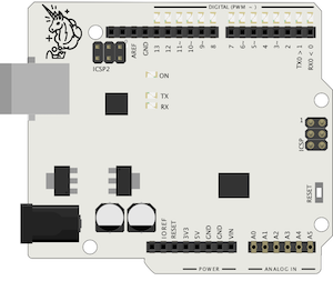
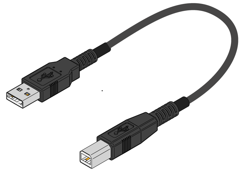
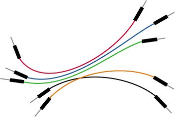
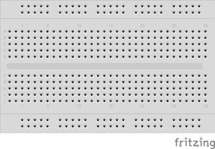
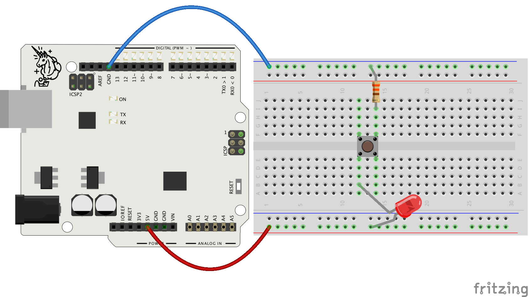
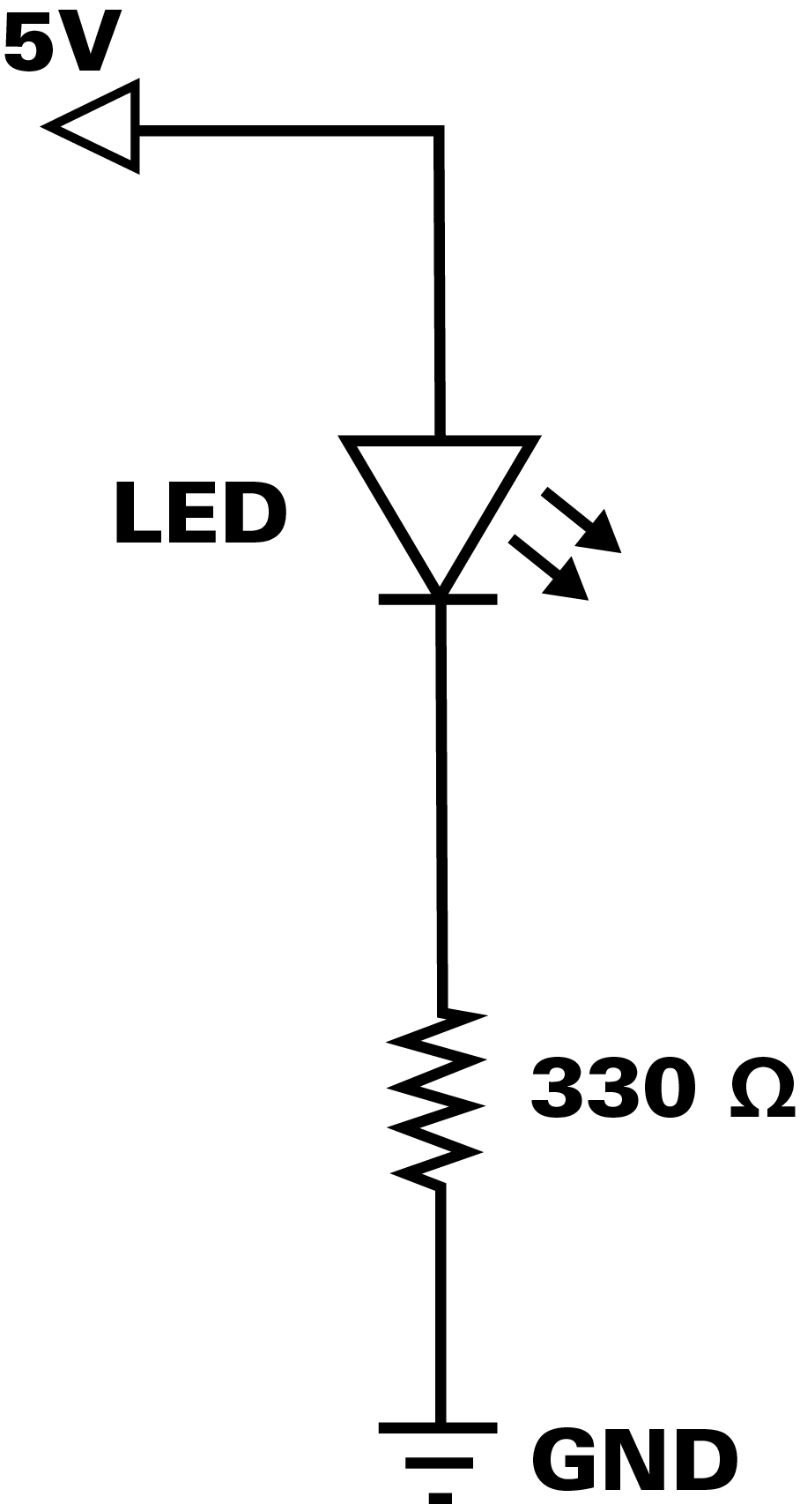
  • ... can make a simple circuit for Arduino
  • ... can navigate in the Arduino programming environment
  • ... can write a simple program and upload it to Arduino
  • ... understands that Arduino programs consist of a code block for the settings of the program (setup) and a block for repeating actions (loop)
  • ... understands that programming commands require arguments to specify what happens when the program is run>
  • ... understands the difference between a passive power pin (5V pin) and a programmable pin (digital pins 0-13)
  • ... grasps the basics of electricity and circuits: closed circuit, voltage, current and resistance
  • ... is able to debug simple errors such as typos
  • ... develops creative perception and project work skills through working with different materials
  • ... to search for programming instructions on the Arduino reference website.
  • ... learns to give and receive constructive feedback in the online environment
  • ... learns to work actively and independently in the online environment

Slides and Lesson Plans

You can use the slides below to introduce this module and especially the first chapter to the students. 

There are similar slides in the Educator Intro of every chapter. 

Plan 1

  • Structured Lesson

    Time      What?
    15 min                                                   Start the module with the slides above. Make sure the students have the electronic components they need and they know who they will be working with.
    15-20 minStudents start the first chapter alone or in pairs and go through the section An Electric Welcome. Instruct the students to discuss any problems they face.
    5 minA small discussion in the class: any challenges so far?
    15-20 min

    Students continue with the material and go through the section Code that Light. Encourage the students to talk to each other about possible problems.

    10 min

    Reflection discussion: What have you learned so far?
    Introduction to the exercises

  • Let the students choose the exercise they like the best
  • Give a time limit: 20 minutes

  • 20 minStudents work on the project. End the lesson (or start the next lesson) by going through a couple of projects the students have made, if they are willing to show them!
    5 minClear the electronics kits. Don't take apart the circuits and projects if it's possible to store them in one piece until the next lesson, especially if the students have unfinished projects.

    Total: 90 - 100 min

    Tweaking the final exercises:
    Option 1

  • shorter: let the students know that they should only finish one final exercise and set a time limit, especially for Exercise 1
  • LEDs Are Awesome
    Option 2
  • longer: Have the students finish both final exercises instead of just one. Encourage the students to craft proper miniatures of lamps in Exercise 1 or traffic light fixtures in Exercise 2.

    Plan 2 - Free-form lesson

    TimeWhat?
    10 min                                                   

    Make sure the students have the electronic components they need.  See that everyone has an access to the material.

    10 min

    Introduce the learning material and the first steps of the chapter on a screen. Set the goal for the first lesson: Complete the first chapter! Introduce the exercise options of the chapter.

     60 minThe students work independently. Walk around in the classroom, observe and support students when they need assistance.
    10 min

    Summary and the end of the lesson.
    - What did you learn?
    - How did you like it?
    - What felt most difficult?
    - Does someone want to show their work?

    Total: 90 min

    Encourage the students to make both Exercise 1 and 2 if you have enough time!

  • Introduction

    Transcript

    Hey hey, nice to meet you! I'm Sanna from Mehackit and you're about to start working on electronics and programming using an Arduino. After these exercises you can start making your very own projects. Maybe you'll want to make a weird musical instrument, an interactive light show, or make stuff move. It's up to you! So - what is Arduino and what is it used for? You're going to use Arduino to detect what's happening around you. Like the lights go out, or somebody moves closer or makes noises or whatnot. And you'll need different sensors and switches to detect those events. Then you'll write simple programs to check what the sensors are detecting and finally, you use that data to control different devices. In real life you would solve maybe everyday problems with electronics and programming, like you would maybe water your plants automatically. People use Arduino for art and expression, like making musical devices. These little devices are also used in interactive exhibitions. You can make cool physical interfaces using Arduino. Prototypes of actual high-tech products are often made and tested with Arduino, before the final product is created. And sometimes even the final product has Arduino technology in it. Arduino is a great example of so-called open technology. Anyone can check out the electronic design of the board and develop it further. So we at Mehackit decided to get our own board which is based on the model Arduino Uno. You can use either device to do these exercises and projects. In addition to the board you'll be using a bunch of electronic components, and we'll start getting to know these components right away. Happy hacking!

    Make sure you have the equipment you need!

    You (or your pair / group) will need:

    Electronic components used in this module:

    • Mehackit Maker Board or an Arduino UNO 
    • breadboard
    • USB A-B cable
    • ~40 x jumper wire (male-male),
      Very practical but not absolutely necessary: ~5 x extension jumper wires (female-female)
    • 3 x push button
    • 4 x LED (red, green, yellow + high brightness LED)
    • 2x light-dependent resistor
    • potentiometer (10kΩ)
    • 180-degree servo motor 
    • piezo speaker
    • resistors: 3 x 330Ω or 3 x 220Ω, 2 x 10kΩ

    Check this video out to see what others have made with Arduino on Mehackit courses and trainings!

    Project examples

    Parts

    Transcript

    Let's make a small light installation with Arduino. This time you won't have to program anything. You'll just use your board as a power source for the LED light. You'll need a set of components for all these assignments so let's go through the first components together. First, of course, you'll need an Arduino Uno or a similar board like this Mehackit Maker Board that I'm going to be using. you'll connect components to these pins on the sides of the board. A USB cable is needed for two reasons. It feeds electricity from the computer to the board and later on, when you write actual computer programs, also data is transferred through the cable. This part is called the breadboard. It's meant for making temporary electric circuits. Have a look: I ripped the sticky tape, from this side, off of this one so you can see how it's made. Every five holes here are connected with metal, which conducts electricity. And also the longer sides are connected. You'll get the hang of connecting things here in no time. If you have the Mehackit Maker Kit, you can attach the maker board and the breadboard next to each other on a piece of acrylic sheet you can find from the kit. I'll show you how how to connect them. To make connections on the breadboard you'll need plenty of colored wires called jumper wires. They make current sort of jump from one row to another, and you can also connect from the breadboard to the Maker Board. Next you will need an LED, any color you like. The LED only conducts electricity to one direction so it has to be connected the right way round. You'll always need a little component called resistor when you connect LEDs to Arduino. They come with different resistances, which means they have a different capability to resist electric current. The color of the stripes here matters. The resistance value is coded into the stripes. So make sure you pick the right one. This time it's orange orange brown and gold. And at last you need a button. Buttons are simple. When it's pressed down current can flow from one side to the other. That's all for now! Go find those parts.

    Do this:

    Find the following parts!

    PartImageDescription
    Mehackit Board (or Arduino UNO)A minicomputer you can program to control light, sound and motors. Connect sensors or switches to make interactive devices.
    USB cable (A/B)You upload the program you have written on the computer to Arduino through the USB cable. Arduino also gets power through it.
    Jumper wiresYou'll need plenty of thin wires of different colors when working with Arduino!
    BreadboardBreadboards are great for making temporary circuits.
    LED 

    LEDs conduct electricity to one direction only. The longer leg is connected towards the 5V pin or later on a programmable digital pin.

    Resistor 330Ω (or 220Ω)

    Resistors resist the flow of an electric current. The value of the resistor is measured in ohms (Ω). The resistance value is coded into the colored stripes (330Ω: orange, orange, brown and gold). You can replace the 330Ω resistor with a 220Ω one.

    Button

    If you're using the parts from the Mehackit Maker Kit, your button is white!


    How do you know what the resistance of a resistor is?

    Educator notes

    • Arduino pins can handle a maximum current of 40mA. Without a resistor it is possible that the LED will break without a resistor, but even more costly, forgetting the resistor can lead to a broken Arduino pin.
    • Resistor value is color coded onto the component itself. If you’re using the Mehackit Maker Kit, the resistor values are depicted on the lid of the kit.
    • If needed, you can check the resistor values from this Sparkfun tutorial. Note: there’s a handy, interactive resistance calculator in the tutorial!
    • It's easy to learn the most common resistor colors, but usually it's not necessary to remember them by heart!

    Your First Circuit


    Do this:

    Make a circuit according to the diagram below.

    Connect your board to the computer with a USB cable

    Test it!

    Circuit diagrams and component images in this module are made with Fritzing 


    What happens when you push the button?

    Educator notes

    • The colors of the wires are not the most essential thing to worry about at this stage.
    • However, as your circuits become more complex, it is a good practice to use red wires for connections that lead to the 5V pin and black / blue wires when connecting to the GND pin. This makes circuits easier to debug.
    • There are three GND pins on the board - it doesn’t matter which of these three is used in a circuit.
    • Don’t worry about the numbers on the breadboard, either! It doesn’t matter which row you connect components to, as long as there are no breaks in the circuit.
    • The LED doesn’t light up? Possible causes:
      • LED is the wrong way round (short pin aka. cathode must be connected towards ground (GND))
      • There’s a break in the circuit: check the connections
      • The resistor is too big - must be 330 or 220 ohms. Check the colored stripes!
    • If the light is constantly on, the button may be connected the wrong way round. Turning it 90 degrees will help!

    Circuits are presented as schematics in engineering and physics. Reading schematics is not taught in the student material - the amount of new things should be kept moderate, and while schematics are a very useful tool, they may not be relevant for all learners.

    The schematic of the first circuit


    Circuits and Electricity

    Transcript

    How does this circuit really work? If the button is not pressed, there's no connection between the start and the end points of the circuit, so there's no electric current. When the button is pressed current flows from the 5v pin to the lowest breadboard row along a wire. Then the current flows through the LED and lights it ,then through the button, the resistor and all the way to the upper row. The last wire connects the circuit to the ground pin. It doesn't really matter which exact breadboard rows you use as long as all the components fit on the breadboard and electricity can flow through all of them. You can choose the color of the wire yourself but it might be wise to connect to the voltage pin with a red wire and to the ground pin with a blue or black wire. When your circuits get more complex than this that will make finding out what's possibly wrong way easier. If your wires are too short you can make them longer with extension wires. But let's go through a few basic electricity terms at this point, and I mean current voltage and resistance. Current always requires a material that conducts electricity, like the copper inside most electric wires. Current can't flow it the circuit is not closed, if there's a break somewhere. There must also be a difference in electric charges between the end points of a circuit or otherwise there will be no current. Current happens when electrons start to flow from one point to another to stabilize the difference. The difference in electric charges is called voltage. The third concept you'll be working a lot with is resistance. Pretty often you need to limit the current in a circuit. For example, Arduino's pins can only handle a small current. That's why you needed a resistor when you connected an LED. Resistors limit the current, some of them just a little and some of them a lot. We'll be working with these things a lot so you get a hang of it in no time, no stress!

    What is required to create an electric current in a circuit?
    Which pin should always be the final point of an Arduino circuit?
    Why is it important to use a 330𝛀 or 220𝛀 resistor when connecting an LED to an Arduino?

    Educator notes

    The explanations on voltage, current and resistance in this module is very compact. These concepts are introduced in the tasks and exercises from a hands-on point of view. 

    However, Arduino is a good tool for teaching the basic physics behind electrical circuits. For example, it is possible to introduce the concept of Ohm's Law after making the first circuit.

    Ohm's Law describes how voltage, current and resistance are related to each other in a circuit:

    voltage = current * resistance

    or in other words:

    U = I * R

    U = voltage (potential difference) in volts (V) I = current in amperes (A) R = resistance in ohms (Ω)

    If you know two of these three quantities, you can calculate the third.

    With Arduino, knowing Ohm's Law can be useful when you need to find the proper resistor for a certain component, such as an LED.  How big of a resistor will you need to limit the current in the circuit so your LED (or the Arduino pin) won't fry?

    For this purpose, you'd use Ohm's Law as follows:

    R = U / I

    With most LEDs, it is safe to assume that they require 20 mA (milliamperes) to function while Arduino's pins can handle max. 40 mA. Let's play safe and aim for the smaller current:

    I = 0.020 A

    A typical LED has a forward voltage of 2.2 V. Forward voltage means the voltage required to get current flowing through the LED. An Arduino pin provides 5V, and when an LED is connected, it will cause a voltage drop of 2.2 V. So the voltage in the circuit should be:

    V = 5 V - 2.2 V = 2.8 V

    The resistor you'll need is:

    2.8 V / 0.020 A = 140 Ω

    It's ok to choose whatever resistor is closest in resistance - as long as the resistance is bigger and not smaller than the result above! Often you'll use 220Ω resistors with an LED, but a 330Ω resistor will work well, too.

    Electronic components are described in datasheets, in which you'll find information like the forward voltage and the required current of the component. Have a look at the datasheet of a basic LED.

    In case you’d like to go deeper into Ohm’s Law and electricity, check out this tutorial by Sparkfun.


    Check Out all Those Other Components

    Transcript

    You will need a bunch of electronic components for the exercises in this module. I'll show you what those components look like. It's always good to have a bunch of different LEDs at hand. You will need at least three LEDs now. With red, yellow and green you can make traffic lights. In addition to light you'll be making sounds and movement. This one here is a piezo speaker. It's needed for making beeping sounds with Arduino. A nice and easy way to produce movement is a servo motor. This one is great - it moves 180 degrees, back and forth. You'll need some resistors with all Arduino projects. Resistors are used with LEDs and with many sensors. Right now you'll only need 3 x 330 ohm resistors and one that has the resistance of 10 kilo-ohms. You can also replace the 330 ohm resistors with 220 ohm ones. That's enough for now but it's good to have a stash of around 10 pieces of each of these resistors for your future projects. Buttons come in many shapes. They may look like this, or this, or something else, and you can actually make your own buttons and switches, too. You'll need three buttons for these exercises. Switches work much like buttons. I'll show you a couple of interesting switches that are a good addition to your selection of components, but you'll be okay with just the button if you can't find other switches. Have a look at these ones. Last but not least, sensors. We'll keep it simple in this section and we'll only use a light dependent resistor, LDR, for detecting light, and a potentiometer which you use by turning the knob. You can, however, use some other sensors, too if you have them around. And in future projects you'll want to use more interesting sensors anyway. Here's a few examples of cool sensors. Depending on where you got the components, you might have some other parts lying around as well. Those you can use in projects after this basic module. For example, these components we have in the Mehackit Maker Kit.

    Which of these is not an electronic component?

    Educator notes

    Note that this video lists all components needed for the entire Electronics and Programming Basics module! Only a fraction is needed for this chapter (one button, three LEDs, three 330/220 ohm resistors).